Tool clamp for machining prism and application method of tool clamp

A tooling fixture and prism technology, applied in the direction of manufacturing tools, metal processing equipment, metal processing machinery parts, etc., can solve the problems of low processing efficiency and inability to guarantee the angle, so as to improve processing efficiency, ensure processing accuracy, and improve work efficiency. Effect

Active Publication Date: 2015-06-03
大宁洋名光电有限公司
View PDF6 Cites 26 Cited by
  • Summary
  • Abstract
  • Description
  • Claims
  • Application Information

AI Technical Summary

Problems solved by technology

Existing optical fixtures can only be turned twice. During processing, the side droop (edge ​​difference) cannot be guaranteed, and the angle cannot be guaranteed, and the processing efficiency is not high.

Method used


Image

  • Tool clamp for machining prism and application method of tool clamp
  • Tool clamp for machining prism and application method of tool clamp
  • Tool clamp for machining prism and application method of tool clamp

Examples


Embodiment Construction

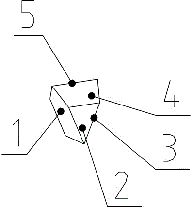
[0020] see figure 1 , the prism has a first refraction surface 1 , a second refraction surface 3 , a first roof surface 4 , a second roof surface 5 and a thickness surface 2 .

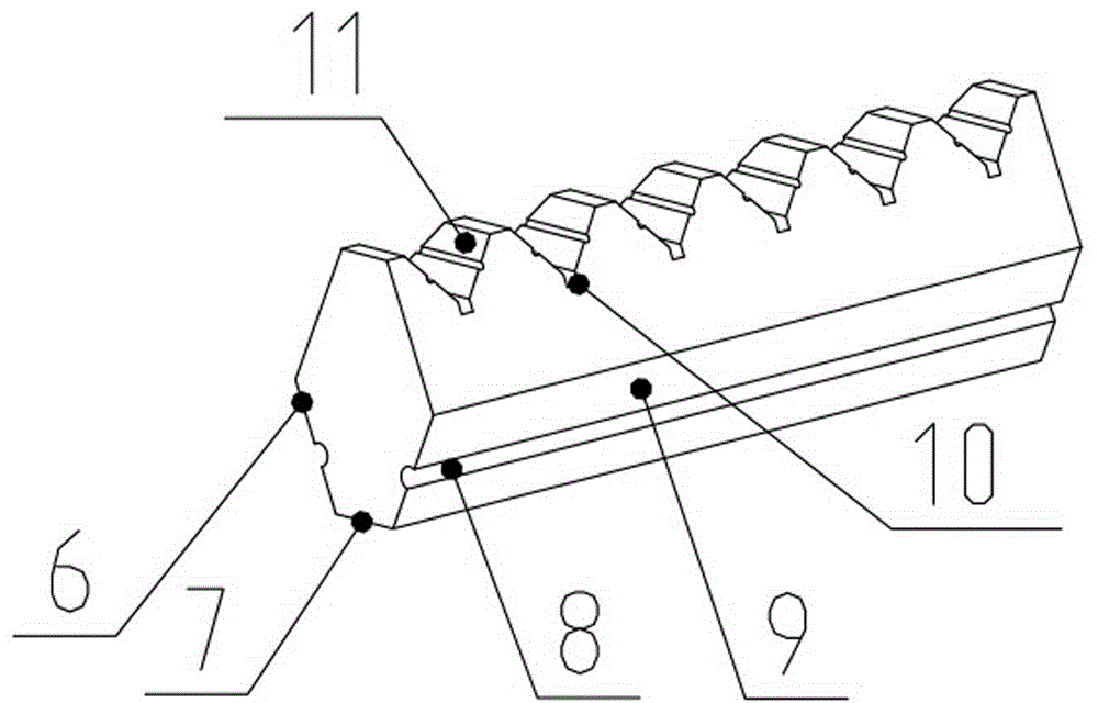
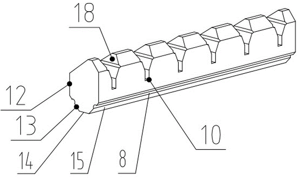
[0021] see figure 2 , image 3 and Figure 4 As shown, a tooling fixture for processing prisms, the tooling fixture includes 21 backing bodies I and 24 backing bodies II fixed with the suction cup of the milling machine; the bottom of the 21 backing bodies I is provided with a first supporting surface 7, Both sides are provided with a first plane 6 and a second plane 9, and the upper part is provided with a plurality of V-shaped grooves 11 on the roof surface. A plane 6 is parallel to the first refraction surface 1 after the prism 19 to be processed is glued to the V-shaped groove 11 on the roof surface, and the second plane 9 is glued to the second refraction surface after the prism 19 to be processed is glued to the V-shaped groove 11 on the roof surface 3 parallel; the bottom of the body II is ...


PUM


Abstract

The invention discloses a tool clamp for machining a prism. The tool clamp comprises a support body I and a support body II which are fixed with the sucker of a milling and grinding machine in a suction manner. A first support face is disposed at the bottom of the support body I, a first plane and a second plane are disposed on two sides of the support body I, the upper portion of the support body I is provided with a plurality of ridge face V-shaped grooves, the first plane is parallel with one reflecting face of the to-be-machined prism adhered to the ridge face V-shaped grooves, and the second plane is parallel with another reflecting face. A second support face is disposed at the bottom of the support body II, a third plane, a fourth plane and a fifth plane are disposed on two sides of the support body II, a plurality of reflecting face V-shaped grooves are formed in the upper portion of the support body II, the fourth plane is parallel with one ridge face of the to-be-machined prism adhered to the reflecting face V-shaped grooves, and the fifthly plane is parallel with another ridge face. Compared with the prior art, the tool clamp has the advantages that the support bodies are provided with multiple turning planes, machining of the multiple planes of the prism is completed at one step by the benchmark after the prism is adhered to the support bodies, machining precision is increased, and machining efficiency is increased.

Description

technical field [0001] The invention relates to the technical field of optical tooling fixtures, in particular to a tooling fixture for processing prisms and a use method thereof. Background technique [0002] Fixture is a kind of technological equipment for clamping workpieces. It is widely used in the manufacturing process that requires cutting, heat treatment, assembly, welding, grinding and testing. The fixtures used on optical grinding equipment are collectively referred to as optical tooling fixtures. In the production of optical products, the fixture is an indispensable process equipment, which directly affects the processing accuracy, productivity and manufacturing cost of the product. In the production of optical parts, the main function of the fixture is to use Workpiece positioning and clamping, correct positioning can ensure the size and position accuracy requirements of workpiece processing, and clamping provides safe and reliable processing conditions for work...

Claims


Application Information

Patent Timeline
Patent Type & Authority Applications(China)
IPC IPC(8): B23Q3/00B24B41/06
CPCB23Q3/00B23Q2703/04B23Q2703/10B24B13/005
Inventor 黄信玉
Owner 大宁洋名光电有限公司
Why Eureka
Try Eureka