
Gantry milling workpiece clamp

A technology of workpiece fixture and workpiece clamp, which is applied in the direction of manufacturing tools, metal processing machinery parts, clamping, etc., can solve the problem that the gantry milling cannot be processed, and achieve the effect of improving the processing accuracy

Inactive Publication Date: 2015-06-03
LIUZHOU YONGYI MACHINERY MFG
View PDF9 Cites 4 Cited by
  • Summary
  • Abstract
  • Description
  • Claims
  • Application Information

AI Technical Summary

Problems solved by technology

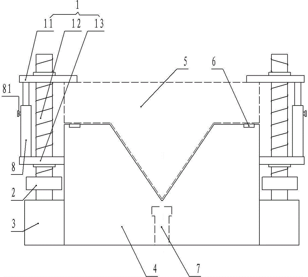
[0003] The technical problem to be solved by the present invention is to provide a fixture for gantry milling workpieces, which can solve the problem that the gantry milling of workpieces with protrusions on the bottom cannot be processed

Method used


Image

  • Gantry milling workpiece clamp

Examples


Embodiment Construction

[0014] The present invention will be described in further detail below in conjunction with accompanying drawing embodiment:

[0015] figure 1 The gantry milling workpiece fixture shown includes a base 4 with a flat bottom surface. The upper end of the base 4 is provided with a concave cavity corresponding to the protrusion at the bottom of the workpiece 5. Both sides of the base 4 are provided with a power machine to drive and clamp the workpiece 5. The work clamp 1, the work clamp 1 includes a first clamping seat 11 and a second clamping seat 13 which are threadedly connected with the screw rod 12, and the second clamping seat 13 is fixedly connected with the side wall of the base 4; the first clamping seat 11 and the second clamping seat 13 are provided with a telescopic guide post 8, the first clamping seat 11 is fixedly connected with one end of the telescopic guide post 8, and the second clamping seat 13 is fixedly connected with the other end of the telescopic guide post...


PUM


Abstract

The invention discloses a gantry milling workpiece clamp, and belongs to the technical field of a tooling clamp. The clamp comprises a base, wherein the bottom surface of the base is a plane, the upper end of the base is provided with a concave cavity corresponding to a bulge arranged at the bottom of a workpiece, the two sides of the base are respectively provided with a workpiece clamp which can clamp the workpiece through being driven by a power machine, each workpiece clamp comprises a first clamping seat and a second clamping seat which are connected with a screw rod through screw threads, the second clamping seat is fixedly connected with the side wall of the base, a telescopic guide post is arranged between the first clamping seat and the second clamping seat, a locking screw is arranged on the telescopic guide post, the power machine is a motor, and one end of the screw thread is connected with an output shaft of the motor through a speed reducer. The gantry milling workpiece clamp can solve the problem that the workpiece provided with the bulge at the bottom surface cannot be processed by the gantry milling.

Description

technical field [0001] The invention relates to the technical field of fixtures, in particular to a workpiece fixture for a gantry milling machine. Background technique [0002] The gantry milling machine is referred to as the gantry milling machine. It is a milling machine with a portal frame and a horizontal long bed. The gantry milling machine includes a portal frame, a horizontal long bed, and a movable workbench on the horizontal long bed. During processing, The workpiece is installed on the worktable and moves longitudinally with the worktable; although the gantry milling machine can process a variety of workpieces, because the table surface of the gantry milling machine is flat, the gantry milling machine can only process workpieces with a flat bottom surface. Workpieces with raised bottom surfaces cannot be machined. Contents of the invention [0003] The technical problem to be solved by the invention is to provide a workpiece fixture for gantry milling, which ca...

Claims


Application Information

Patent Timeline
Patent Type & Authority Applications(China)
IPC IPC(8): B23Q3/06
CPCB23Q3/06B23Q17/005B23Q2717/006
Inventor 陈玉昆石磊吴焕
Owner LIUZHOU YONGYI MACHINERY MFG
Learn More