Machine tool

A technology for machine tools and clamping arms, which is applied in the field of machine tools and can solve the problem that the clamping arms cannot be restored to the swinging action.

Active Publication Date: 2015-06-03
BROTHER KOGYO KK
View PDF7 Cites 14 Cited by
  • Summary
  • Abstract
  • Description
  • Claims
  • Application Information

AI Technical Summary

Problems solved by technology

In this state, the clamping arm cannot return to normal swinging action

Method used


Image

  • Machine tool
  • Machine tool
  • Machine tool

Examples


Embodiment Construction

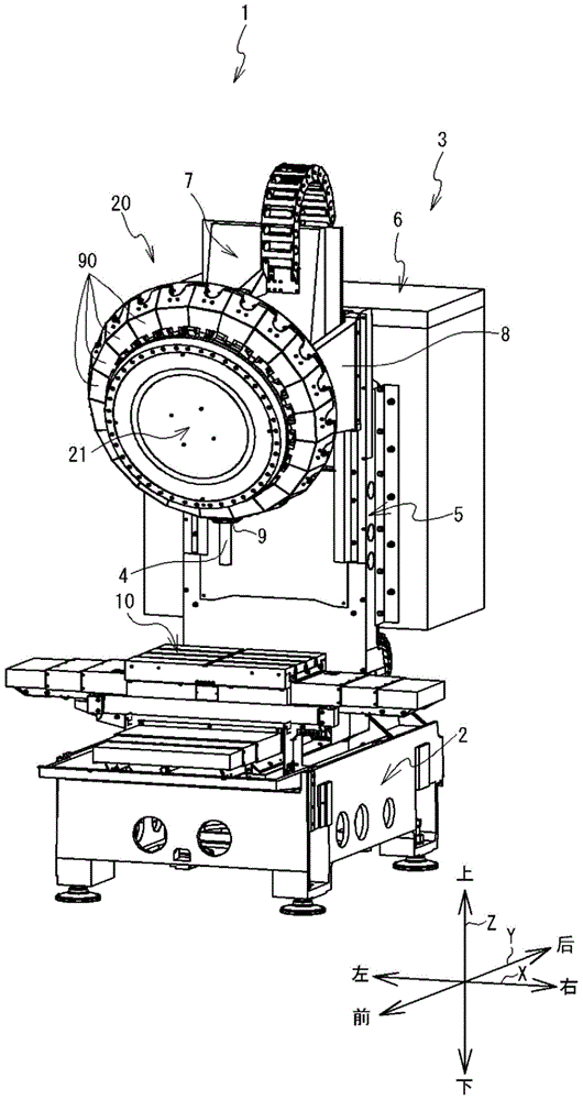
[0029] Embodiments of the present invention will be described with reference to the drawings. The following description uses up and down, left and right, and front and rear as indicated by arrows in the figure. The left-right direction, front-rear direction, and up-down direction of the machine tool 1 are the X-axis direction, the Y-axis direction, and the Z-axis direction of the machine tool 1, respectively. The Z-axis origin is the mechanical origin of the Z-axis. The machine origin is a position where the machine coordinates of the X-axis and the Y-axis are zero, and the machine coordinates of the Z-axis reach the upper limit of the machined object.

[0030] refer to figure 1 The structure of the machine tool 1 will be described. The machine tool 1 includes a machine base 2, a machine tool body 3, a workbench 10, a tool changing device 20, and the like. The base 2 is a substantially rectangular parallelepiped metal base. The machine tool main body 3 is provided behind ...


PUM


Abstract

The invention relates to a machine tool. The machine tool has a tool magazine. Multiple clamping arms that can swing are arranged at the periphery of a main body of the tool magazine. The main body of the tool magazine is provided with guide components that correspond to the multiple clamping arms in position. Steel balls arranged on the rear ends of the clamping arms slide on guide surfaces of the guide components. The guide surfaces are bent in a substantially arc manner and are bent by surrounding axes of the clamping arms. During tool changing, when the steel balls are disconnected from grooves in the guide surfaces, the steel balls slide toward the other end of the guide surfaces, and stop in bent positions of the guide surfaces. Cam driven parts arranged on the clamping arms are arranged below cam surfaces of auxiliary cams positioned on a main shaft head. When the main shaft head drops in the above state, the cam driven parts abut against the cam surfaces of the auxiliary cams, and the clamping arms recover and can swing normally.

Description

technical field [0001] The invention relates to a machine tool. Background technique [0002] The machine tool has a tool changer. The tool changer is a device for exchanging tools mounted on the spindle. The tool changing device has a tool magazine. The tool magazine has a tool magazine main body, a plurality of clamping arms, a plurality of fulcrum tables, and the like. A plurality of clamping arms are radially arranged along the outer periphery of the main body of the tool magazine. The plurality of fulcrums are respectively fixed to the outer periphery of the tool magazine main body, and support the clamp arm so that the clamp arm can swing. The clamping arm has a gripping portion at one end. The handle is attached to the holding portion so that the handle holding the knife can be detachably attached. The clamp arm has a first cam follower and a second cam follower near the fulcrum table, and the first cam follower and the second cam follower face the spindle head ...

Claims


Application Information

Patent Timeline
Patent Type & Authority Applications(China)
IPC IPC(8): B23Q3/155
CPCB23Q3/15513B23Q3/1552
Inventor 山元达央
Owner BROTHER KOGYO KK
Why Eureka
Try Eureka