LED lamp radiator for vehicle

A technology of LED lamps and radiators, which is applied in motor vehicles, road vehicles, vehicle parts, etc., and can solve the problem that LED lamps cannot work for a long time, the contact area between the heat dissipation cover and the air is small, and the light intensity of LED lamps is weakened, etc. problems, to meet the needs of rapid heat conduction, convenient wiring and embedding, and low production costs

Inactive Publication Date: 2015-06-03
SUZHOU CHENGYUAN PHOTOELECTRIC TECH
View PDF6 Cites 4 Cited by
  • Summary
  • Abstract
  • Description
  • Claims
  • Application Information

AI Technical Summary

Problems solved by technology

[0002] LED lamps have the advantages of small size, low power consumption, online programming and flexibility, and are gradually accepted by consumers. There are more and more applications in automotive lights. Only when multiple The light intensity generated by the LED lamps working at the same time can meet the requirements of the car lights, but multiple LED lamps work at the same time and the adjacent distance is small, so that the heat generated is relatively large. If the heat dissipation is not timely, it will directly affect the normal operation of the LED lamps. , which puts higher requirements on the heat dissipation performance of LED lamps
For example, the application number 201310114336.6 discloses a grease heat dissipation LED lamp, which includes an LED lamp and a heat dissipation cover. The heat dissipation cover is made of a heat c

Method used


Image

  • LED lamp radiator for vehicle
  • LED lamp radiator for vehicle

Examples


Embodiment Construction

[0013] In order to make the technical means, creative features, goals and effects achieved by the present invention easy to understand, the present invention will be further described below in conjunction with specific embodiments.

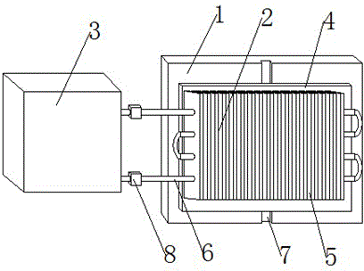
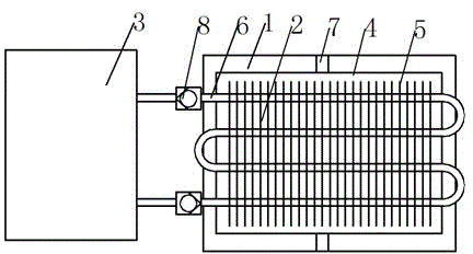
[0014] Such as figure 1 and figure 2 As shown, a radiator for a vehicle LED lamp includes a lamp holder 1 and a cooling cylinder 3, the lamp holder 1 is in the shape of a long plate, and the inner surface of the lamp holder 1 is provided with a heat dissipation base 2, and the heat dissipation base 2 is composed of Composed of copper long plate 4 and heat sink 5, the thickness of the long plate 4 is 1.1-1.3mm, the heat sink 5 is equidistantly arranged in parallel on the long plate 4, the long plate 4 is connected to the inner surface of the lamp holder 1 , the thickness of the heat sink 5 is 1.6-2.2mm, the middle of the heat sink 5 is detoured with a cooling pipe 6, the cooling pipe 6 is connected to the cooling cylinder 3, and the copper long p...


PUM

PropertyMeasurementUnit
Thicknessaaaaaaaaaa

Abstract

The invention discloses an LED lamp radiator for a vehicle and relates to the technical field of LED lamps. The LED lamp radiator for the vehicle comprises a lamp holder and a cooling cylinder, wherein the lamp holder is of a long plate shape, the inner side surfaces of the lamp holder are provided with a radiating substrate which is composed of a long copper plate and radiating fins, the thickness of the long plate is 1.1-1.3mm, the radiating fins are arranged on the long plate at equal intervals, the long plate is connected with the inner side surfaces of the lamp holder, the thickness of each radiating fin is 1.6-2.2mm, and cooling pipes penetrate the cooling fins back and force and are connected with the cooling cylinder. The radiating fins are thin in thickness and large in area so that the thermal conductivity is improved. The contacting area with the air is large so that rapid air cooling can be realized. Conversion current is formed by the cooling liquid which is due to the temperature difference and rapid flow so that fast cooling of the radiating fins can be realized and the radiating speed is improved. The cooling cylinder is used for storing and backflowing the cooling liquid and providing power to drive the flow of the cooling liquid so that the flowing speed of the cooling liquid can be fastened.

Description

technical field [0001] The invention belongs to the technical field of LED lamps, in particular to a heat sink for LED lamps for vehicles. Background technique [0002] LED lamps have the advantages of small size, low power consumption, online programming and flexibility, and are gradually accepted by consumers. There are more and more applications in automotive lights. Only when multiple The light intensity generated by the LED lamps working at the same time can meet the requirements of the car lights, but multiple LED lamps work at the same time and the adjacent distance is small, so that the heat generated is relatively large. If the heat dissipation is not timely, it will directly affect the normal operation of the LED lamps. , which puts forward higher requirements on the heat dissipation performance of LED lamps. For example, the application number 201310114336.6 discloses a grease heat dissipation LED lamp, which includes an LED lamp and a heat dissipation cover. The...

Claims


Application Information

Patent Timeline
IPC IPC(8): F21V29/56F21V29/89F21W101/02F21Y101/02F21W107/10
CPCF21S45/46F21W2107/10
Inventor 戴岳平
Owner SUZHOU CHENGYUAN PHOTOELECTRIC TECH
Why Eureka
Try Eureka