
Magnetostrictive displacement sensing flowmeter and flow measuring method

A magnetostrictive and flowmeter technology, applied in the direction of volume/mass flow generated by electromagnetic effects, can solve the problems of inability to realize automatic control, flowmeter measurement error, high maintenance cost, etc., achieve high reliability, eliminate pulsation, and resist Strong pollution effect

Inactive Publication Date: 2015-06-03
SHANGHAI LIXIN HYDRAULIC
View PDF7 Cites 4 Cited by
  • Summary
  • Abstract
  • Description
  • Claims
  • Application Information

AI Technical Summary

Problems solved by technology

Although there are new precision flow measurement and test components coming out at home and abroad, the direct contact measurement in the use process has strict pollution control requirements for the used medium.
Any contamination of the medium will cause measurement error or failure of the flowmeter, short service life, and high maintenance costs. Especially in the factory test of hydraulic components, the internal leakage of hydraulic components is a must-test index. When the internal leakage assessment index is small in milliliters The measurement of flow has become a difficult problem in the factory. Usually, the measurement is performed by manually observing the number of oil droplets, which is time-consuming and laborious, and cannot realize automatic control. These problems have prompted people to continuously explore and improve the internal leakage automatic detection measuring instrument and test of the component test process. method

Method used


Image

  • Magnetostrictive displacement sensing flowmeter and flow measuring method
  • Magnetostrictive displacement sensing flowmeter and flow measuring method
  • Magnetostrictive displacement sensing flowmeter and flow measuring method

Examples


Embodiment Construction

[0031] The preferred embodiments of the present invention are given below in conjunction with the accompanying drawings to describe the technical solution of the present invention in detail.

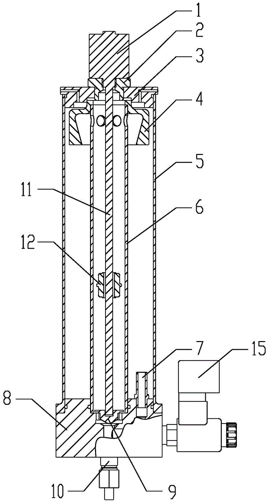
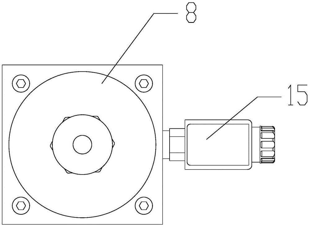
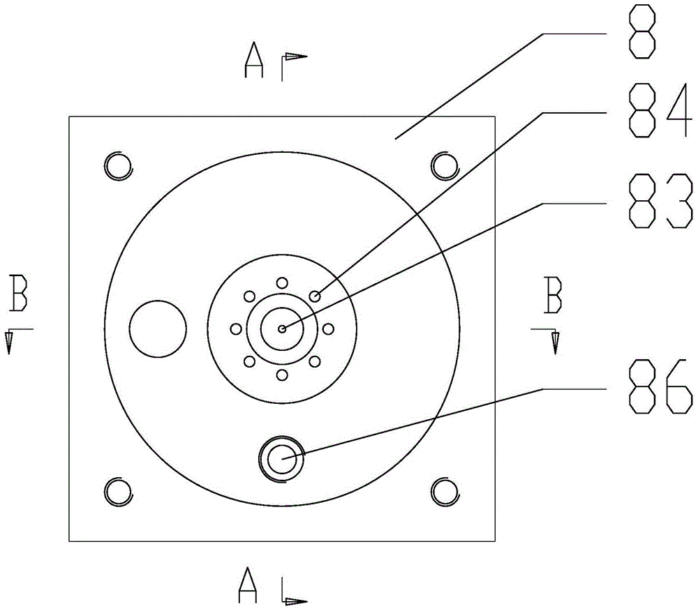
[0032] Such as Figure 1-Figure 7 As shown in the figure, a magnetostrictive displacement sensor flowmeter includes a sensor electronic chamber 1, a transition joint 2, a tank cover 3, an overflow tank 5, a metering barrel 6, a valve block 8, a damping gasket 9, a straight joint 10, and a measurement The waveguide 11 and the magnetic ring buoy 12 are characterized in that: the measuring waveguide 11 is a circular magnetostrictive material with a copper wire inside, the lower end of the measuring waveguide 11 is connected to the damping washer 9, the upper end of the measuring waveguide 11 is connected to the The sensor electronic warehouse 1 is connected, and the magnetic ring buoy 12 is freely movably set on the measurement waveguide 11. At the same time, the measurement waveguide 11 is...


PUM


Abstract

The invention relates to a magnetostrictive displacement sensing flowmeter. The magnetostrictive displacement sensing flowmeter comprises a sensor electronic bin, a transitional joint, a groove cover, an overflow groove, a metering barrel, a valve block, a damping washer, a straight joint, a measuring wave guide tube and a magnetic ring buoy. The magnetic ring buoy is driven to move in the up-down direction by change of the liquid level of leakage oil, a magnetostrictive effect of a magnetostriction material is achieved, the measuring wave guide tube deforms elastically so that a mechanical wave which is expanded towards two sides is generated, the mechanical wave is received by the sensor electronic bin which is connected with the upper end of the measuring wave guide tube and is converted into an electric signal, and the volume flow of the leakage oil is calculated by comparison and conversion. Owing to the magnetostrictive effect, the magnetostriction property of the magnetostrictive displacement sensing flowmeter is not changed along with time. The magnetostrictive displacement sensing flowmeter has the advantages of high stability, high reliability, high response speed, high resolution precision, non-contact measurement, zero abrasion, long service life and the like. Moreover, the magnetostrictive displacement sensing flowmeter is particularly suitable for measuring micro flow.

Description

technical field [0001] The invention relates to a flow detection device and a flow measurement method, in particular to a flow meter and a flow measurement method for small flow measurement with fast response speed, high resolution precision, non-contact measurement, no wear and long service life. Background technique [0002] In hydraulic engineering, the measurement of small flow has always been a technical problem that plagues the hydraulic industry. Although there are new and precise flow measurement test components coming out at home and abroad, the direct contact measurement in the use process has strict pollution control requirements for the used medium. Any contamination of the medium will cause measurement error or failure of the flowmeter, short service life and high maintenance costs. Especially in the factory test of hydraulic components, the internal leakage of hydraulic components is a must-test index. When the internal leakage assessment index is small in mill...

Claims


Application Information

Patent Timeline
IPC IPC(8): G01F1/56
Inventor 袁才富高建中彭沪海邹昌建崔剑闵剑庭仇芝宇李青英汤淳诚朱金强
Owner SHANGHAI LIXIN HYDRAULIC
Learn More