Test stand for power systems of automobiles, and automatic test method of working conditions

A power system and test bench technology, applied in vehicle testing, machine/structural component testing, measuring devices, etc., can solve problems such as the impracticality of dynamic working condition simulation, and achieve the effect of strong authenticity

Inactive Publication Date: 2015-06-03
ZHENGZHOU YUTONG BUS CO LTD
View PDF11 Cites 31 Cited by
  • Summary
  • Abstract
  • Description
  • Claims
  • Application Information

AI Technical Summary

Problems solved by technology

[0010] The purpose of the present invention is to provide a kind of automobile power system test bench and working condition automatic

Method used


Image

  • Test stand for power systems of automobiles, and automatic test method of working conditions
  • Test stand for power systems of automobiles, and automatic test method of working conditions
  • Test stand for power systems of automobiles, and automatic test method of working conditions

Examples


Embodiment 1

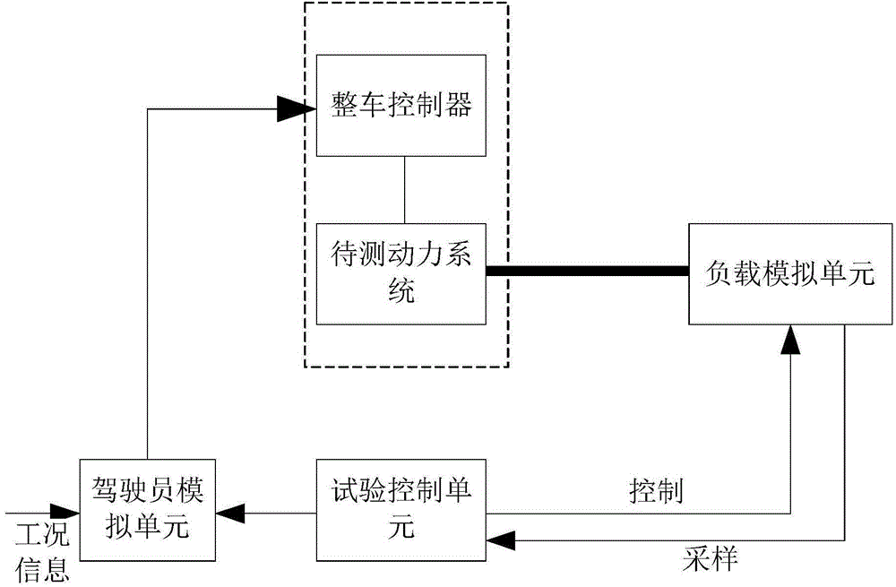
[0036] like figure 1 As shown, a vehicle powertrain test bench includes:

[0037] The load simulation unit is used to simulate the road load and is connected to the drive system to be tested; the load simulation unit is generally selected as a controlled rotating device, such as a dynamometer.

[0038] The test control unit is used to control the load simulation unit; the test control unit is based on vehicle information set in advance, such as vehicle weight, windward area, road resistance and other parameters, and at the same time according to the current actual vehicle speed, using the principle of vehicle dynamics to calculate The resistance suffered by the vehicle is transmitted to the load simulation unit in the form of target torque.

[0039] A driver simulation unit, the input interface of the driver simulation unit is used to input working condition information, and is also provided with a control interface for connecting with the vehicle controller of the power syst...

Embodiment 2

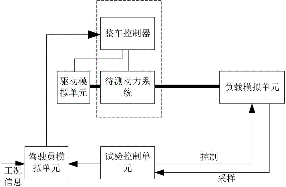
[0045] like figure 2 As shown, the difference from Embodiment 1 is that the test bench further includes a driving simulation unit for simulating the driving equipment. The driving equipment refers to the engine, driving motor, etc. If the driving simulation unit simulates the engine and the power system to be tested is an electric power system, the test system as a whole simulates a hybrid power system.

[0046] In Embodiment 1, the vehicle controller can exert control on the power system to be tested, specifically to control the driving mechanism in the power system to be tested. In embodiment 2, because the driving simulation unit is added, in order to control the acceleration and deceleration of the power system to be tested, it is also necessary to control the driving simulation unit.

[0047] If the driving simulation unit simulates the motor, the vehicle controller can control the driving simulation unit for simulating the motor through the corresponding motor controll...

Embodiment 3

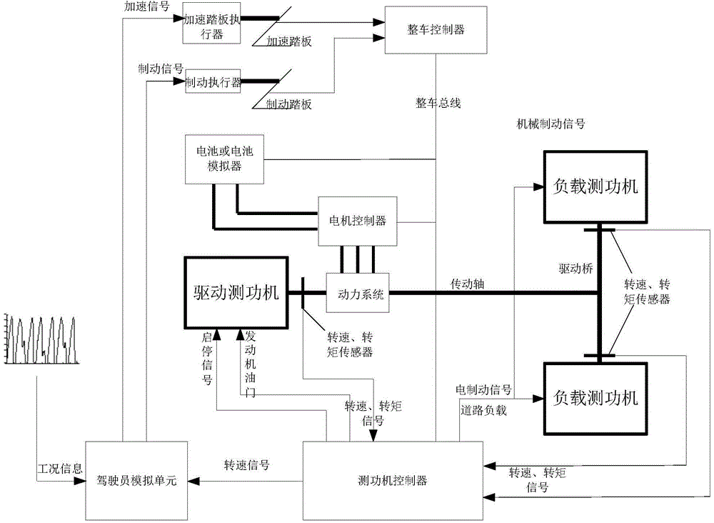
[0052] The difference between this embodiment and embodiment 2 is:

[0053] First, the control interface of the driver simulation unit is connected to the vehicle controller through the execution device. The above-mentioned actuators refer to the accelerator pedal actuator and the brake actuator. The acceleration signal and the brake signal generated by the driver simulation unit are sent to the accelerator pedal actuator and the brake actuator respectively, and they respectively control the accelerator pedal and the brake pedal. . Both the accelerator pedal and the brake pedal are part of the vehicle whose power system is to be tested, and this form can also take into account the testing of the accelerator pedal and the brake pedal. In addition, the brake pedal is also associated with the vehicle's mechanical brake mechanism, thereby enabling testing of the mechanical brake mechanism as well.

[0054] Second, the test control unit (in this embodiment, the test control unit ...


PUM


Abstract

The invention relates to a test stand for power systems of automobiles, and an automatic test method of working conditions. The test stand for the power systems of the automobiles comprises a load simulation unit, a test control unit and a driver simulation unit, wherein the load simulation unit is used for simulating road loads, and is connected with a power system to be tested in a transmission manner; the test control unit is used for controlling the load simulation unit; the input interface of the driver simulation unit is used for inputting the information of working conditions, and the driver simulation unit is provided with a control interface for being connected with a whole-vehicle controller of the power system to be tested and an interface for acquiring actual vehicle speed; the information of working conditions at least comprises real-time given vehicle speed; the driver simulation unit generates control signals through the comparison of the actual vehicle speed and the given vehicle speed, and the whole-vehicle controller receives the control signals, so that the power system can run according to the real-time given vehicle speed. According to the automatic test method of working conditions, any operation of a driver is not needed, and the full automatic test is realized.

Description

technical field [0001] The invention relates to an automobile power system test bench and a working condition automatic testing method of the power system. Background technique [0002] The performance of electric vehicles is closely related to the operating conditions, and its performance varies greatly under different operating conditions. Therefore, the power system of electric vehicles is usually designed based on specific operating conditions. As the infrastructure for the development of the electric vehicle power system, the test bench must have the function of dynamic working condition simulation; the general dynamometer test bench working condition simulation function is realized by manually operating the electric pedal and the load regulator, which can only be performed simply The simulation of steady-state working conditions does not have the function of simulating dynamic working conditions, and needs to be improved urgently. [0003] The Chinese patent document ...

Claims


Application Information

Patent Timeline
IPC IPC(8): G01M17/007
Inventor 李飞强高建平李维国李高鹏朱光海苏常军杨学青李欣欣刘振楠
Owner ZHENGZHOU YUTONG BUS CO LTD
Why Eureka
Try Eureka