
Circumferential fixed-width cutting path planning method for rough machining of integrated impeller

A technology of integral impeller and tool path, applied in the direction of digital control, electrical program control, etc., can solve the problems of poor cutting state of the tool, low processing efficiency, redundant tool path, etc.

Active Publication Date: 2015-06-03
HUAZHONG UNIV OF SCI & TECH
View PDF5 Cites 12 Cited by
  • Summary
  • Abstract
  • Description
  • Claims
  • Application Information

AI Technical Summary

Problems solved by technology

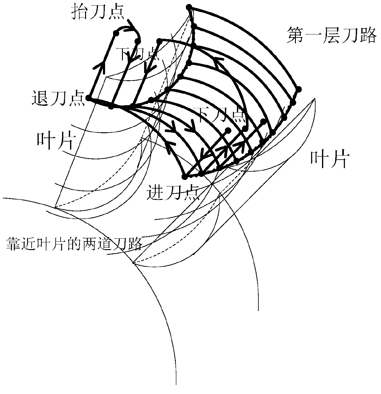
[0004] The present invention aims at providing a new overall impeller rough machining circumferential orientation method for the defects and deficiencies existing in the planning method of the overall impeller rough machining tool path, such as redundant tool paths, low processing efficiency, and poor cutting state of the tool. The planning method of the wide cutting tool path adopts circumferential continuous cutting tool, which avoids redundant tool paths, significantly improves the rough machining efficiency of the overall impeller, and keeps the tool in a positive forward cutting state most of the time, reducing tool wear. Extended tool life with good overall roughing effect

Method used


Image

  • Circumferential fixed-width cutting path planning method for rough machining of integrated impeller
  • Circumferential fixed-width cutting path planning method for rough machining of integrated impeller
  • Circumferential fixed-width cutting path planning method for rough machining of integrated impeller

Examples


Embodiment Construction

[0053] In order to make the object, technical solution and advantages of the present invention clearer, the present invention will be further described in detail below in conjunction with the accompanying drawings.

[0054] The fixed cutting width in the circumferential direction of the present invention means that the effective cutting path in the cutting path in the flow channel is along the circumferential direction of the integral impeller, and the cutting width of the circumferential cutting path is equal in the axial direction, that is, the fixed cutting width.

[0055] The planning method of the overall impeller rough machining circumferential fixed cutting width cutting path of the present invention comprises the following steps (1) to (9):

[0056] Step (1), generate the tool path source file. Determine the number of layers M of the cutting layer of the flow channel according to the depth of the flow channel and the machining tool, and then generate two axial cutting ...


PUM


Abstract

The invention discloses a circumferential fixed-width cutting path planning method for the rough machining of an integrated impeller. The method comprises the following steps: generating a tool path source file of an axial cutting tool path, and analyzing position coordinates and a tool axis vector of each tool position point; equally dividing the axial cutting tool path into delta according to an axial width; interpolating circumferential cutting tool paths between the corresponding equal dividing tool position points on the axial cutting tool path; calculating a tool position point top rake tendency of each circumferential cutting tool path, and determining feeding points and retraction points on the basis of the tool position point top rake tendencies; interpolating a lowering point and a lifting point of each circumferential cutting tool path; interpolating a connecting tool path between every two adjacent circumferential cutting tool paths; connecting the axial cutting tool path with each circumferential cutting tool path to obtain an integrated cutting path according to a cutting sequence. According to the planning method, by the cutting path for the rough machining of the integrated impeller, the phenomenon of tool path redundancy is avoided, high effective cutting rate is achieved, a cutting tool is kept in a positive top rake cutting state most of the time, abrasion can be effectively reduced, and the cutting tool can be protected.

Description

technical field [0001] The invention belongs to the field of multi-axis linkage numerical control machining, and more specifically relates to a planning method for a circumferential fixed-cut width tool path for rough machining of an integral impeller. Background technique [0002] Compared with the impeller with assembled structure, the integral impeller has the advantages of simple structure, good heat transfer performance, high reliability and light weight, so it is widely used in various high-performance aero-engines. It is complex and difficult to process. Therefore, although multi-axis linkage CNC machine tools can be used for processing at present, the processing quality is poor, the efficiency is low, and the processing cost is high, which seriously restricts the use of the overall impeller. The processing of the integral impeller generally includes the stages of rough forging, rough machining, finishing, polishing, etc., among which the amount of material removal in...

Claims


Application Information

Patent Timeline
Patent Type & Authority Applications(China)
IPC IPC(8): G05B19/19
CPCG05B19/4103
Inventor 严思杰鄢龙志代星丁汉唐祥武
Owner HUAZHONG UNIV OF SCI & TECH
Learn More