Power Feeding Coil Unit And Wireless Power Transmission Device
A technology of power transmission coil and power reception coil, which is applied to battery circuit devices, circuit devices, coils, etc., can solve the problems of power transmission efficiency decline and power transmission efficiency reduction, and achieve the effect of suppressing the decline of power transmission efficiency.
- Summary
- Abstract
- Description
- Claims
- Application Information
AI Technical Summary
Problems solved by technology
Method used
Image
Examples
no. 1 Embodiment approach
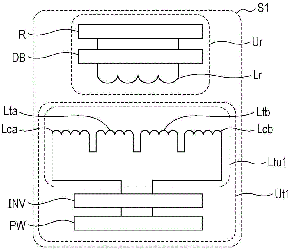
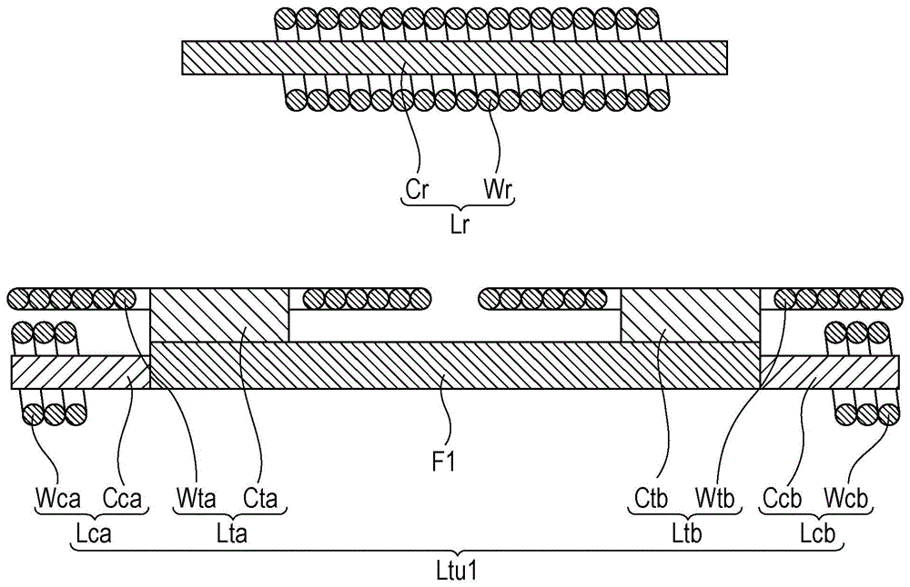
[0041] First, refer to figure 1 and figure 2 The configuration of the wireless power transmission device S1 according to the first embodiment of the present invention will be described. figure 1 It is a system configuration diagram showing the wireless power transmission device according to the first embodiment of the present invention together with loads. figure 2 It is a cross-sectional view showing the power transmission coil unit and the power reception coil according to the first embodiment of the present invention.
[0042] Such as figure 1 As shown, the wireless power transmission device S1 includes a wireless power transmitting device Ut1 and a wireless power receiving device Ur.
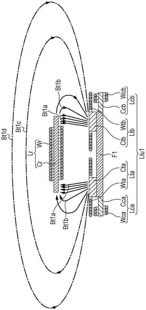
[0043] The wireless power transmission device Ut1 includes a power supply PW, an inverter INV, and a power transmission coil unit Ltul. The power supply PW supplies DC power to an inverter INV described later. The power supply PW is not particularly limited as long as it outputs DC po...
no. 2 Embodiment approach
[0069] Below, refer to Figure 4 as well as Figure 5 The arrangement of the wireless power transmission device S2 according to the second embodiment of the present invention will be described. Figure 4 It is a system configuration diagram showing a wireless power transmission device according to a second embodiment of the present invention together with a load. Figure 5 It is a cross-sectional view showing a power transmission coil unit and a power reception coil according to a second embodiment of the present invention.
[0070] Such as Figure 4 As shown, the wireless power transmission device S2 includes a wireless power transmitting device Ut2 and a wireless power receiving device Ur.
[0071]The wireless power transmission device Ut2 includes a power supply PW, an inverter INV, and a power transmission coil unit Ltu2. The arrangement of the power supply PW and the inverter INV is the same as that of the wireless power transmission device S1 according to the first e...
no. 3 Embodiment approach
[0088] Below, refer to Figure 7 as well as Figure 8The arrangement of the wireless power transmission device S3 according to the third embodiment of the present invention will be described. Figure 7 It is a system configuration diagram showing a wireless power transmission device according to a third embodiment of the present invention together with a load. Figure 8 It is a cross-sectional view showing a power transmission coil unit and a power reception coil according to a third embodiment of the present invention.
[0089] Such as Figure 7 As shown, the wireless power transmission device S3 includes a wireless power transmitting device Ut3 and a wireless power receiving device Ur.
[0090] The wireless power transmission device Ut3 includes a power supply PW, an inverter INV, and a power transmission coil unit Ltu3. The arrangement of the power supply PW and the inverter INV is the same as that of the wireless power transmission device S1 according to the first embo...
PUM
 Abstract
Description
Claims
Application Information
 - R&D
- Intellectual Property
- Life Sciences
- Materials
- Tech Scout
- Unparalleled Data Quality
- Higher Quality Content
- 60% Fewer Hallucinations
Browse by: Latest US Patents, China's latest patents, Technical Efficacy Thesaurus, Application Domain, Technology Topic, Popular Technical Reports.
© 2025 PatSnap. All rights reserved.Legal|Privacy policy|Modern Slavery Act Transparency Statement|Sitemap|About US| Contact US: help@patsnap.com


