U-shaped wireless power transmission coupled structure and design method thereof

A technology of wireless power transmission and coupling structure, applied in electrical components, circuit devices, electromagnetic wave systems, etc., can solve problems such as unsatisfactory transmission efficiency, and achieve the effect of convenient installation and improved transmission efficiency

Active Publication Date: 2015-06-03
重庆前卫无线电能传输研究院有限公司
View PDF4 Cites 14 Cited by
  • Summary
  • Abstract
  • Description
  • Claims
  • Application Information

AI Technical Summary

Problems solved by technology

[0004] In the research process of wireless power transfer technology, the research hotspots of most scholars are how to realize the precise positioning of the transmitting coil and the pickup coil, how to realize the adaptive control of the load, and few people pay attention to how to improve the wireless power transfer coupling structure to improve the system Even if someone improves the coupling structure of wireless power transmission, it is often limited to changing the shape of the magnetic core and the winding method of the coil. The system is still coupled by two coils, and the transmission efficiency is still not ideal.

Method used


Image

  • U-shaped wireless power transmission coupled structure and design method thereof
  • U-shaped wireless power transmission coupled structure and design method thereof
  • U-shaped wireless power transmission coupled structure and design method thereof

Examples


Embodiment Construction

[0027] The specific implementation manner and working principle of the present invention will be further described in detail below in conjunction with the accompanying drawings.

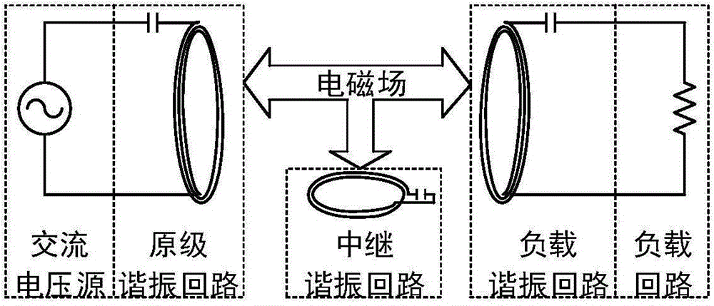
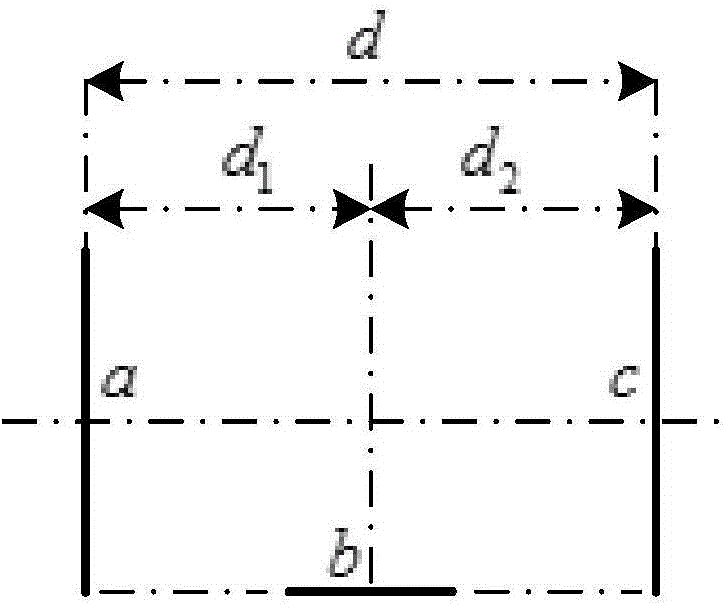
[0028] Such as Figure 2-Figure 3 As shown, a U-shaped wireless power transmission coupling structure includes a first coil, a second coil and a third coil, wherein: the first coil is used as the primary resonant circuit coil, and the second coil is used as the relay resonant circuit coil and is connected with the middle Following the fixed connection of the resonant capacitor, the third coil is used as the coil of the load resonant circuit. When performing wireless power transmission, the coil end faces of the first coil, the second coil and the third coil form a U-shaped structure, and the second coil is located on the first between the coil and the third coil.

[0029] combine image 3 It can be seen that the end faces of the first coil and the third coil are facing each other and coaxially arra...


PUM


Abstract

The invention discloses a U-shaped wireless power transmission coupled structure and a design method thereof. The structure is characterized by comprising a first coil, a second coil and a third coil, wherein the first coil is used as a primary resonance loop coil, the second coil is used as a relay resonance loop coil and fixedly connected with a relay resonance capacitor, and the third coil is used as a load resonance loop coil; when wireless power transmission is carried out, a U-shaped structure is formed by the coil end surfaces of the first coil, the second coil and the third coil, and the second coil is positioned between the first coil and the third coil. The structure has the effects that the traditional double-coil induction coupled structure is changed, the transmission efficiency of the wireless power transmission system is improved through the additional arrangement of a relay resonance loop, and the coupled structure is very convenient to mount, particularly for an electric vehicle wireless charging system.

Description

technical field [0001] The present invention relates to wireless power transfer technology (Wireless Power Transfer, WPT), in particular to a U-shaped wireless power transfer coupling structure and a design method thereof. Background technique [0002] Wireless power transmission technology is a new technology that transmits energy to loads through electromagnetic coupling, which can realize wireless power supply from power supply to load. For the inductively coupled wireless power transmission system, the coupling structure is a key module to realize wireless power transmission, and its design is related to various indicators such as the transmission distance, transmission range and transmission efficiency of the WPT system. [0003] Such as figure 1 As shown, the traditional wireless power transfer system usually consists of a DC power supply (E dc ), high frequency inverter module (S 1 ~S 4 ), primary resonant circuit (L p 、C p ), load resonant circuit (L s 、C s )...

Claims


Application Information

Patent Timeline
Patent Type & Authority Applications(China)
IPC IPC(8): H02J17/00H02J50/12H02J50/50
CPCH02J7/025
Inventor 孙跃叶兆虹唐春森王智慧戴欣苏玉刚
Owner 重庆前卫无线电能传输研究院有限公司
Why Eureka
Try Eureka