Electrical junction box

A technology for electrical connection boxes and boxes, which is applied in the direction of electrical components, circuits or fluid pipelines, transportation and packaging, etc. It can solve the problems of being introduced into the inside of the cover, easy to stay in the flange part, and unable to promote drainage, so as to improve drainage sexual effect

Active Publication Date: 2015-06-03
SUMITOMO WIRING SYST LTD
View PDF4 Cites 3 Cited by
  • Summary
  • Abstract
  • Description
  • Claims
  • Application Information

AI Technical Summary

Problems solved by technology

[0004] However, since the flange portion protrudes outward in a direction perpendicular to the side wall of the main body, for example, when water adhering to the surface of the cover due to wetness or the like flows down from above, there is a tendency for the water to flow downward. There is a problem that it is easy to stay on the flange part before falling
Moreover, as in Patent Document 1 figure 1 As shown, since the gap between the flange part and the peripheral wall end surface of the cover that abuts on the flange part from above is small, the water stagnant in the flange part may be introduced into the inside of the cover through the small gap through the capillary phenomenon. sex
[0005] In addition, it is also considered that water enters the inside of the cover from the fuse mounting part formed by opening on the upper surface of the cover. However, since the gap between the flange part and the end surface of the peripheral wall of the cover is very small, even if the Water drains from this gap to the outside, which may also not be facilitated due to the surface tension of the water

Method used


Image

  • Electrical junction box
  • Electrical junction box
  • Electrical junction box

Examples


Embodiment Construction

[0031] Hereinafter, embodiments of the present invention will be described with reference to the drawings.

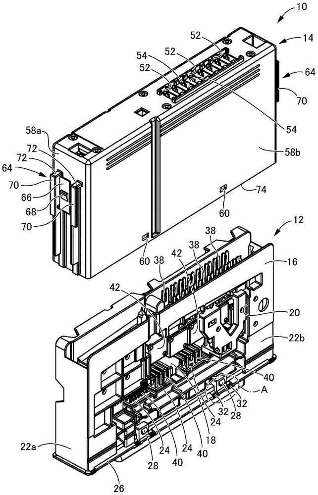
[0032] first, figure 1 The electrical junction box 10 which is one embodiment of this invention is shown. The electrical connection box 10 includes a main body 12 and a cover 14 , and the box-shaped cover 14 opened downward is inserted and attached to the main body 12 from above, whereby the main body 12 is housed and assembled in the cover 14 . The electrical connection box 10 is housed in another electrical connection box such as a relay box, for example, and is mounted on vehicles such as automobiles.

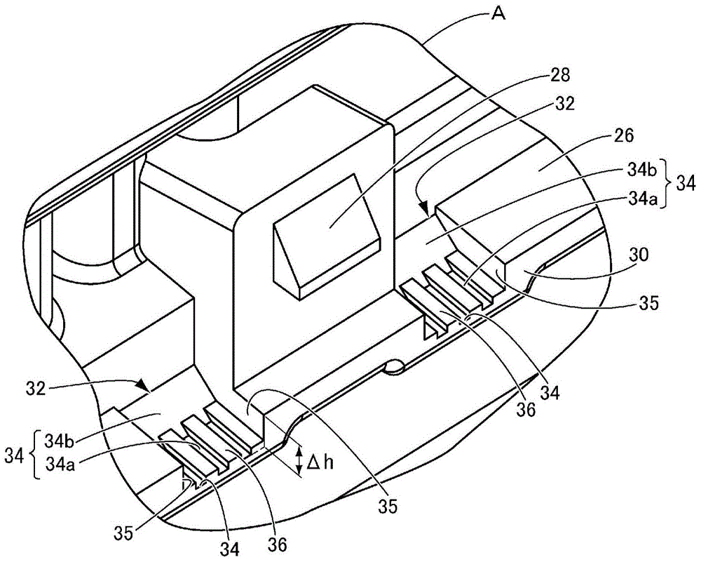
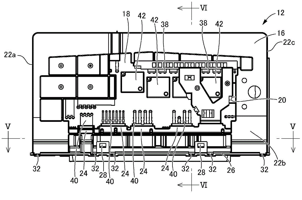
[0033] Figure 2 ~ Figure 6 The main body portion 12 is shown. The main body portion 12 has a vertically long rectangular block shape as a whole. The main body 12 has a structure in which a printed circuit board 18 as an internal circuit is assembled in a housing 16 made of synthetic resin. In addition, the internal circuit is not limited to the printed circuit ...


PUM


Abstract

Provided is an electrical junction box with a novel structure, said electrical junction box having a downward-opening, box-shaped cover that is externally fitted from above to a main body equipped with an internal circuit, wherein drainage in a gap between a flange and a peripheral wall end face disposed on the main body is improved. A recess (32) that is recessed downward is disposed on a portion of the surface of the flange (26), and opens to a protruding end face (30) of the flange (26). A drainage hole (76) is formed between the recess (32) and the peripheral wall end face (74) of the cover (14). Meanwhile, forming surfaces (34) of the drainage hole (76) are configured to include rough surface parts (36).

Description

technical field [0001] The present invention relates to an electrical connection box in which a box-shaped cover opened downward is externally attached to a main body portion provided with an internal circuit from above. Background technique [0002] In the past, in electrical equipment systems such as automobiles, an electrical junction box in which electrical components such as fuses and relays are arranged with good space efficiency is used in an appropriate place, and is effectively connected from a battery to various electrical equipment. power supply, distribution and control. As such an electrical connection box, for example, as described in Japanese Patent Application Laid-Open No. 2012-100476 (Patent Document 1), there is known an electrical connection box having a structure in which a box-shaped cover opened downward is inserted and attached to the box from above. The main body is equipped with an internal circuit composed of a printed circuit board or the like. ...

Claims


Application Information

Patent Timeline
Patent Type & Authority Applications(China)
IPC IPC(8): H02G3/14B60R16/02H02G3/16
CPCB60R16/0239H02G3/081H02G3/088H02G3/14
Inventor 阿南修一
Owner SUMITOMO WIRING SYST LTD
Why Eureka
Try Eureka