CT scan perfusion method and device

A technology of CT scanning and CT value, which is applied in computerized tomography scanners, echo tomography, etc., can solve the problems of poor compliance and hinder the practical application of CT perfusion technology, and achieve good compliance, simple and easy operation, and reduce radiation effect of dosage

Active Publication Date: 2015-06-10
中国人民解放军总医院第八医学中心
View PDF9 Cites 18 Cited by
  • Summary
  • Abstract
  • Description
  • Claims
  • Application Information

AI Technical Summary

Problems solved by technology

Therefore, the subjects need to hold their breath for a long time (about 30s) during the scanning process to reduce the influence of respiratory motion artifacts. Some subjects cannot cooperate and their compliance is poor, which also hinders the traditional CT scan. Practical application of perfusion technology

Method used


Image

  • CT scan perfusion method and device
  • CT scan perfusion method and device
  • CT scan perfusion method and device

Examples


no. 1 approach

[0020] Next, in the CT scanning perfusion method of the present invention, in order to obtain the increase Q of the CT value in the organ caused by the contrast medium perfusion, before injecting the contrast medium, a CT plain scan is performed on the organ of the subject. In the description, this method is referred to as dual-phase (plain scan phase and arterial phase) CT perfusion, and this is taken as an example to describe the composition of the present invention in detail.

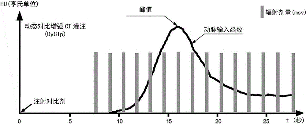
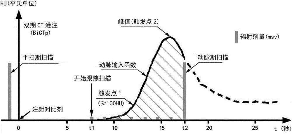
[0021] figure 1 It is a dynamic data scanning diagram showing an embodiment of dual-phase CT perfusion of the present invention. exist figure 1 In , the abscissa is the time axis, the point at which the contrast agent starts to be injected is set as time 0, and the ordinate represents the CT value (HU).

[0022] The specific implementation steps of the dual-phase CT perfusion performed on the subject are performed in the following order.

[0023] (flat scan)

[0024] Before injecting contrast med...

no. 2 approach

[0053] In the second embodiment, except that the steps of "scanning and tracking" and "arterial phase scanning" are slightly different from those of the first embodiment, the content of other steps is the same as that of the first embodiment, and their descriptions are omitted here.

[0054] The differences between the second embodiment and the first embodiment in the "scan tracking" step and the "arterial phase scan" step will be mainly described below.

[0055] In the "scanning and tracking" step of the second embodiment, during the scanning and tracking of the iodine contrast agent with a low radiation dose, the change of CT value with time is depicted as the time density curve of the artery (arterial input function), which is consistent with the first In one embodiment, after the CT value of the artery reaches a certain threshold (trigger point 1), a predetermined time is delayed, and then the arterial phase scanning of the conventional radiation dose is started on the arte...

no. 3 approach

[0057] The increase Q of the CT value, when used in dual-source CT or spectral CT, is obtained from the arterial phase scan through dual-energy subtraction or spectral subtraction.

[0058] The third embodiment is that when the CT scanning perfusion method of the present invention is used for dual-energy CT (dual-source CT) or energy spectral CT, the "scanning in the plain scan" is omitted, and the increase Q of the CT value is obtained by scanning the arterial phase. Except for the direct acquisition of dual-energy subtraction or spectral subtraction, it is the same as the first embodiment, and the description of the same parts will be omitted here.


PUM


Abstract

The invention provides a CT scan perfusion method and device. The method includes the following steps: after a prescribed time t1 has passed since injection of a contrast agent, carrying out a single-slice CT tracking scan of the contrast agent concentration in the artery with a first radiation dosage; during scan tracking, trigging a scan program when a trigger point is reached, and carrying out an arterial phase scan of a visceral organ at a time t2 with a second radiation dosage, which is larger than the first radiation dosage, so as to obtain an arterial phase CT value; obtaining a CT value increment according to the arterial phase CT value; setting a time density curve of the contrast agent in the artery as an arterial input function during the contrast agent scan tracking process, and obtaining the blood flow volume of the visceral organ according to the arterial input function and the CT value increment. The CT scan perfusion method avoids repeated scans of the visceral organ in the traditional method, so as to reduce radiation on a human body, achieve simpler and easier operations and accurate results, and lessen the discomfort of an examinee.

Description

technical field [0001] The invention relates to a CT scanning perfusion method and device. Background technique [0002] Traditional dynamic-contrast CT perfusion (DyCTp) uses multi-phase dynamic scanning after injection of (iodine) contrast agent, often including 10-20 repeated CT scans with relatively fixed time intervals (1-2s). Then use the denser dynamic scan data mentioned above to obtain the arterial input function (the time density curve of the contrast agent in the aorta or its large branches) and the time density curve of the contrast agent in each voxel within the scan range, through the maximum slope method and deconvolution The blood flow of each voxel can be obtained by the volumetric method; especially in the whole organ perfusion imaging (measurement), the dynamic scanning coverage of the DyCTp method is the entire organ, that is to say, repeat 10-20 CT scans for the entire organ At this time, the X-ray radiation received by the subject is several times to d...

Claims


Application Information

Patent Timeline
Patent Type & Authority Applications(China)
IPC IPC(8): A61B6/03
Inventor 袁小东敖国昆全昌斌李红张静
Owner 中国人民解放军总医院第八医学中心
Why Eureka
Try Eureka