Pipe fitting bulge machining device and method

A technology for processing devices and pipe fittings, applied in metal processing equipment, forming tools, manufacturing tools, etc., can solve the problems of inability to process multiple bulges from metal mandrels, and achieve a simple structure, improve work efficiency, and simplify structural design. Effect

Active Publication Date: 2015-06-10
NINGBO YONGXIANG COPPER PIPELINE
View PDF5 Cites 19 Cited by
  • Summary
  • Abstract
  • Description
  • Claims
  • Application Information

AI Technical Summary

Problems solved by technology

[0008] The above processing method has the following disadvantages: this method can only process one bulge, and it is impossible to process multiple bulges in one stroke of the metal mandrel.

Method used


Image

  • Pipe fitting bulge machining device and method
  • Pipe fitting bulge machining device and method
  • Pipe fitting bulge machining device and method

Examples


specific Embodiment approach

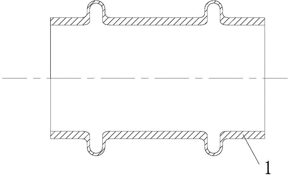
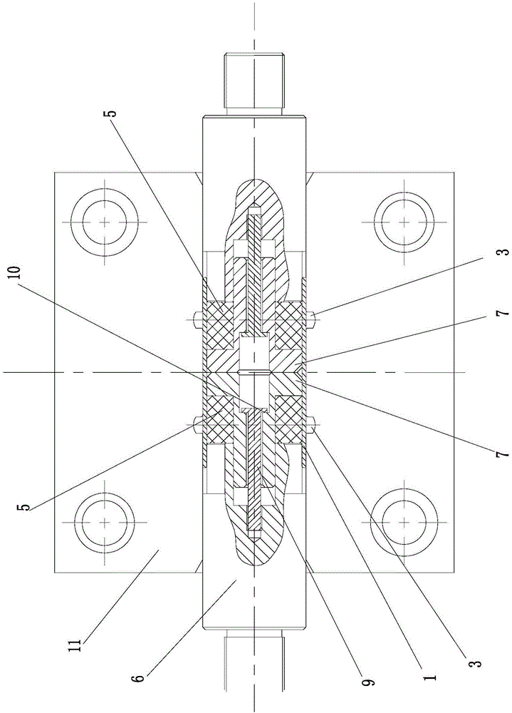
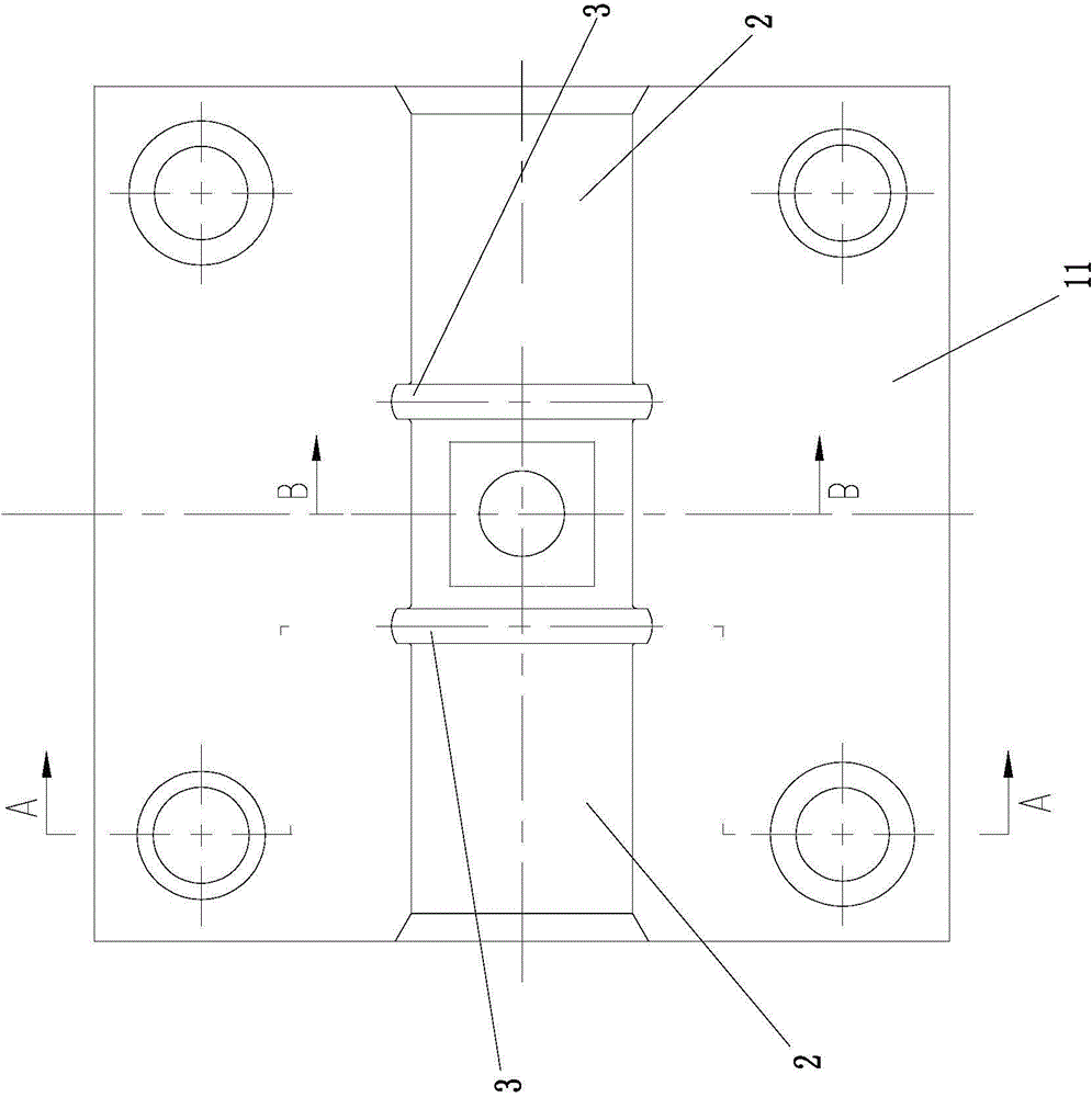
[0038] A device for processing bulges on pipe fittings, which includes a mold base composed of an upper mold base and a lower mold base 11 compressed by a pressing device, and a plurality of guide columns can be added between the upper mold base and the lower mold base 11 to improve The movement stability of the upper mold base, the mold base is provided with an accommodating cavity 2 for accommodating pipe fittings 1, and two annular grooves 3 are arranged at axial intervals in the accommodating cavity 2; the accommodating cavity There are two sets of extruding assemblies with the same structure and opposite movement directions for simultaneously forming two bulges on the pipe fitting 1 in sliding fit within 2 . The pressing device can be a common machine tool, such as a vertical extruder, a cold heading machine and the like. Specifically, the accommodating cavity 2 referred to here includes the upper accommodating cavity in the upper mold base and the lower accommodating cav...


PUM


Abstract

The invention discloses a pipe fitting bulge machining device and method. The pipe fitting bulge machining device comprises a die seat composed of an upper die seat and a lower die seat which are tightly pressed, wherein the die seat is provided with a containing cavity (2) for containing a pipe fitting (1); two annular grooves (3) are formed in the containing cavity (2) in the axial direction at interval; the containing cavity (2) is internally matched with two groups of extrusion assemblies at interval, and the extrusion assemblies have the same structure and opposite movement directions and are used for molding two bulges on the pipe fitting (1) at the same time. The invention provides the pipe fitting bulge machining device which can be used for machining the two budges at the same time and has a simple die seat structure, and the machining method thereof.

Description

technical field [0001] The invention relates to the technical field of processing devices for bulges on pipe fittings, in particular to a device for processing bulges on pipe fittings and a processing method thereof. Background technique [0002] In the industry, a bulge refers to an annular radial protrusion formed by extrusion on the pipe wall. It is a very common process to process bulges on pipe fittings. The most widely used processing device is: the mold base is provided with a groove for accommodating pipe fittings, and the groove is provided with an annular groove for bulge forming. One end of the groove is provided with a stopper for limiting the position of the pipe fitting. The inner wall of the pipe fitting is slidably fitted with a metal mandrel. [0003] In the tube bulge processing device with this structure, the tube is placed in the groove, one end of the tube is pressed against the stopper, and the driving device drives the metal mandrel to move until the ...

Claims


Application Information

Patent Timeline
Patent Type & Authority Applications(China)
IPC IPC(8): B21D15/06B21D37/10
Inventor 严二张继宏
Owner NINGBO YONGXIANG COPPER PIPELINE
Why Eureka
Try Eureka