Spindle driving device of vertical type powerful spinning machine and driving method

A powerful spinning and spindle-driven technology, which is applied in transmission devices, mechanical equipment, belts/chains/gears, etc., can solve the problems of reducing the mechanical efficiency of spinning machines, slow switching of spindles, and low efficiency, so as to save manpower and improve Mechanical efficiency, reducing the effect of the transmission link

Inactive Publication Date: 2015-06-10
KUNSHAN LONGYUN AUTO PARTS
View PDF6 Cites 0 Cited by
  • Summary
  • Abstract
  • Description
  • Claims
  • Application Information

AI Technical Summary

Problems solved by technology

[0003] 1. After multiple sets of gear transmission, the mechanical efficiency of the spinning machine will be greatly reduced;
[0004] 2. The horizontal gearbox switches between high and low speeds through internal gear displacement, which has the problem of slow switching between high and low gears of the spindle speed and low efficiency;
[0005] 3. Assembling and debugging multiple sets of transmission gears inside the bed is time-consuming and laborious, and maintenance is difficult

Method used


Image

  • Spindle driving device of vertical type powerful spinning machine and driving method
  • Spindle driving device of vertical type powerful spinning machine and driving method
  • Spindle driving device of vertical type powerful spinning machine and driving method

Examples


Embodiment 1

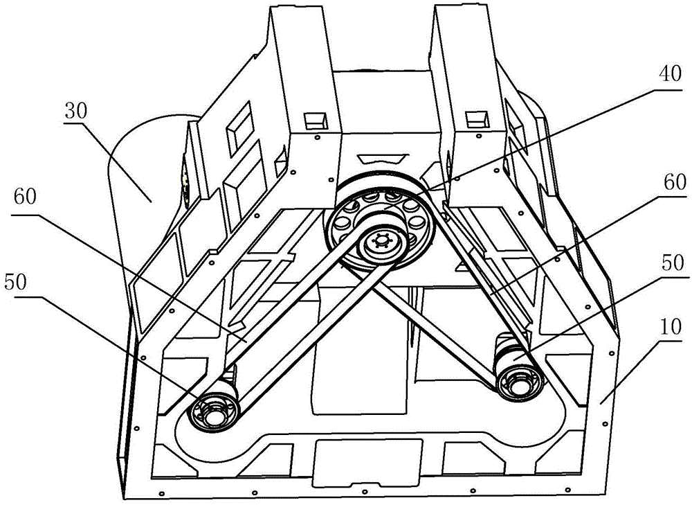
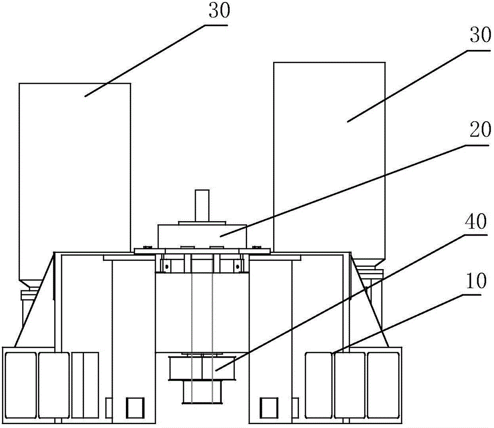
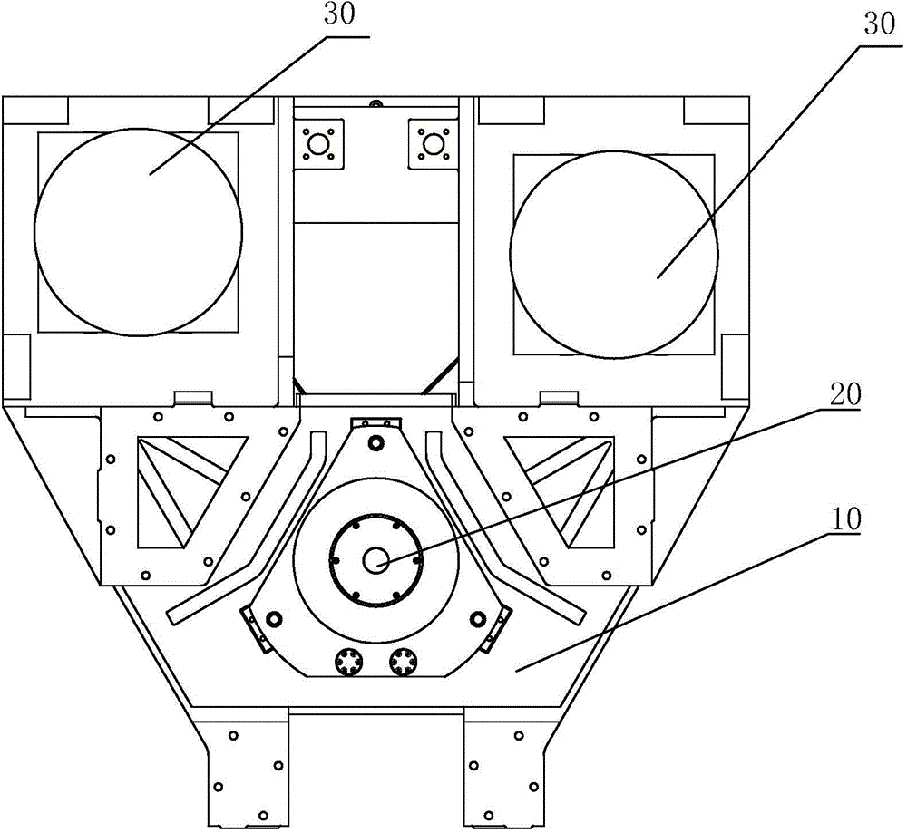
[0027] Such as Figure 1 to Figure 4 As shown, the main shaft driving device of the vertical powerful spinning machine of this embodiment includes: a bed 10, a main shaft 20, multiple sets of drive motors 30, and a control system for controlling the drive motors 30 (not shown in the figure) ), the spindle 20 is vertically mounted on the bed 10, the multiple groups of drive motors 30 are also vertically mounted on the bed 10, and the output end of each group of the drive motors 30 is mounted with a first With a pulley 50, a second pulley 40 is installed at the bottom of the main shaft 20, and each group of the first pulley 50 and the second pulley 40 are connected by a flexible transmission body 60. The diameters of the positions on the second pulley 40 corresponding to different flexible transmission bodies 60 are different from each other. Specifically, different flexible transmission bodies 60 are connected to different positions of the second pulley 40, and the diameters at...

Embodiment 2

[0036] The difference between this embodiment and the first embodiment is that the diameters of the second pulley 40 corresponding to the positions of the flexible transmission bodies 60 are all the same, while the diameters of the multiple groups of the first pulleys 50 are different. The multiple sets of the first pulley 50, the flexible transmission body 60, and the second pulley 40 constitute different reduction ratios, so that the driving motor 30 provides different rotation speeds for the main shaft 20.


PUM


Abstract

The invention discloses a spindle driving device of a vertical type powerful spinning machine and a driving method. The device comprises a lathe bed, a spindle, multiple groups of drive motors and a control system used for controlling the drive motors, wherein the spindle is vertically mounted on the lathe bed; the multiple groups of drive motors are vertically mounted on the lathe bed; a first belt wheel is mounted at the output end of each group of drive motor; a second belt wheel is mounted at the bottom of the spindle; each first wheel and the second belt wheel are connected through a flexible transmission body; diameters of the positions, corresponding to different transmission bodies, of the second belt wheel are different, or diameters of the multiple first wheels are different. The multiple groups of drive motors which are vertically mounted are adopted as power sources for high-speed and low-speed switching of the spindle, a servo system can switch different motors rapidly, and high-speed and low-speed switching of the spindle is rapid; meanwhile, a horizontal transmission can be omitted, and the cost is saved.

Description

Technical field [0001] The invention relates to a vertical powerful spinning machine, in particular to a main shaft driving device and a driving method of the vertical powerful spinning machine. Background technique [0002] In the spinning forming industry, to realize rough and fine flexible processing of different types of parts, the spindle of the spinning machine needs to rotate at different speeds. Most of the existing spinning machines use a motor connected to a horizontal gearbox, and the horizontal gearbox is used to convert the high and low speed of the main shaft. The output end of the gearbox is connected to the gear inside the bed to connect the horizontal gear of the motor. The power is transferred to the spindle after the rotation is converted into a form of rotation. The following problems exist in the form of horizontal gearbox: [0003] 1. After multiple sets of gear drives, the mechanical efficiency of the spinning machine will be greatly reduced; [0004] 2. The...

Claims


Application Information

Patent Timeline
Patent Type & Authority Applications(China)
IPC IPC(8): B21D22/14F16H7/02
CPCB21D22/14F16H7/02
Inventor 安健王波张凤操
Owner KUNSHAN LONGYUN AUTO PARTS
Why Eureka
Try Eureka