
Dynamic control method and device for electromagnetic stirring position at solidification end in continuous casting of steel

A technology of electromagnetic stirring and solidification end, applied in the field of continuous casting production control of iron and steel metallurgy, can solve the problems of affecting temperature and thickness, maintain stability, and the effect of electromagnetic stirring at the end of solidification is not obvious, and achieve the effect of improving internal quality.

Active Publication Date: 2015-06-10
NORTHEASTERN UNIV
View PDF6 Cites 19 Cited by
  • Summary
  • Abstract
  • Description
  • Claims
  • Application Information

AI Technical Summary

Problems solved by technology

However, the continuous casting production process is usually difficult to keep completely stable, and the change of continuous casting process parameters will directly affect the electromagnetic stirring effect
In particular, the change of continuous casting steel type and casting speed will significantly affect the temperature and thickness of the liquid core of the slab in the electromagnetic stirrer at the end of solidification, thereby affecting the effect of electromagnetic stirring at the end of solidification
For this reason, the traditional method of installing an electromagnetic stirrer at the solidification end at a fixed position cannot fully meet the production requirements of continuous casting. The electromagnetic stirring effect at the solidification end is not obvious, and the internal quality of the slab is unstable, making it difficult to meet the production requirements of high-quality continuous casting slabs.

Method used


Image

  • Dynamic control method and device for electromagnetic stirring position at solidification end in continuous casting of steel
  • Dynamic control method and device for electromagnetic stirring position at solidification end in continuous casting of steel
  • Dynamic control method and device for electromagnetic stirring position at solidification end in continuous casting of steel

Examples


Embodiment Construction

[0031] An embodiment of the present invention will be described in detail below in conjunction with the accompanying drawings.

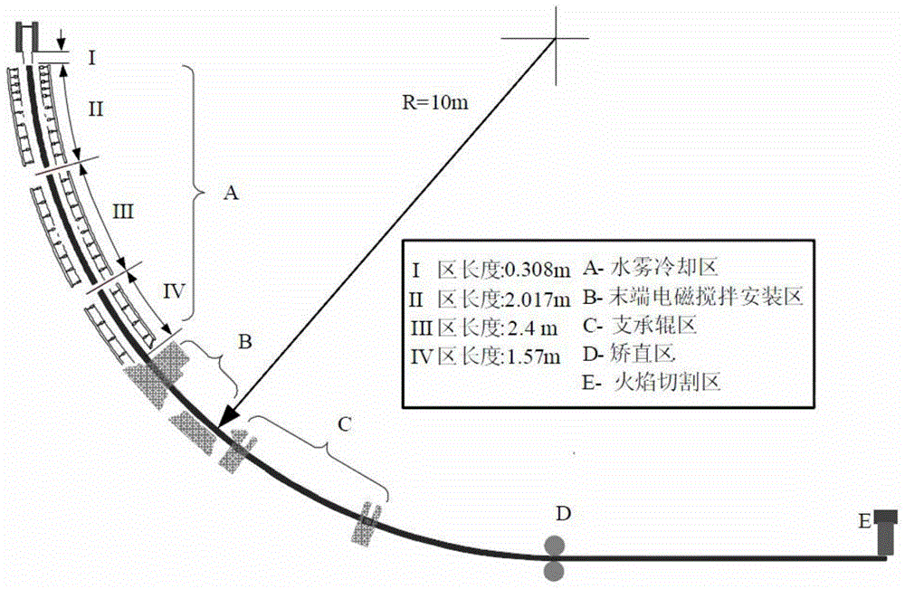
[0032] Such as figure 1 The billet continuous casting machine of a steel mill in China shown has ten streams, including the crystallizer area and four secondary cooling areas (such as figure 1 Zone I, Zone II, Zone III and Zone IV shown) and an air-cooled zone, in which the crystallizer has a total height of 0.9m and an effective height of 0.8m. The lengths of secondary cooling zone 1 to secondary cooling zone 4 are 0.308m, 2.071m, 2.4m and 1.57m respectively. The billet size is 160mm×160mm.

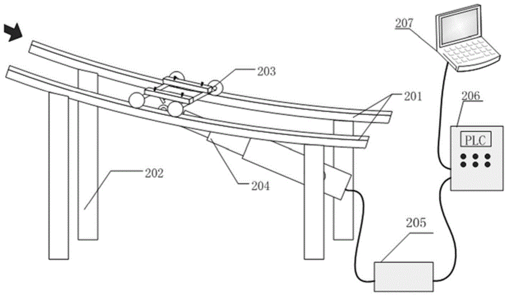
[0033] In this embodiment, the dynamic control device for the electromagnetic stirring position at the solidification end of steel continuous casting is specially designed for the dynamic control method of the electromagnetic stirring position at the solidification end of steel continuous casting implemented on the billet continuous caster figure 2 As shown...


PUM


Abstract

The invention discloses a dynamic control method and device for an electromagnetic stirring position at a solidification end in continuous casting of steel, and belongs to the field of iron and steel metallurgy continuous casting production control. A continuous casting dynamic tracking model is established by adopting a double linked list comprising continuous casting tracking units, continuous casting process parameters are acquired in real time, and solidification information of a continuous casting billet is calculated. By comparing a current electromagnetic stirring position with an optimal electromagnetic stirring position, the displacement required by a solidification-end electromagnetic stirrer is calculated in real time and the solidification-end electromagnetic stirrer is guaranteed to be always in an optimal stirring position of the cast steel. The device comprises an arc-shaped guide rail, a slide mechanism, a drive mechanism and a controller, wherein the solidification-end electromagnetic stirrer is fixedly mounted on the slide mechanism; the slide mechanism is positioned on the arc-shaped guide rail; one end of the drive mechanism is connected with the slide mechanism, and the other end of the drive mechanism is connected with the controller. The dynamic control method and device better solve a difficult problem of incapability of adjusting a conventional solidification-end electromagnetic stirrer in real time along with a continuous casting process, and are good in field implementation effect.

Description

technical field [0001] The invention belongs to the field of iron and steel metallurgical continuous casting production control, and in particular relates to a dynamic control method and device for the electromagnetic stirring position at the solidification end of steel continuous casting. Background technique [0002] Due to the difference in the solubility of solute elements in the solid-liquid two phases, the solidification dendrite growth process of steel continuous casting is accompanied by the exclusion of solute elements from the solid phase to the liquid phase, and gradually enriched between the dendrite arms to form solute micro-segregation. At the same time, the solidification shrinkage of the slab at the end of solidification and the bulging of the slab between the rolls can easily cause the molten steel rich in segregation elements to gather at the center of the slab to form serious central segregation, which is difficult to effectively eliminate in the later heat...

Claims


Application Information

Patent Timeline
IPC IPC(8): B22D11/115B22D11/18
CPCB22D11/115B22D11/18
Inventor 罗森朱苗勇姜东滨王卫领
Owner NORTHEASTERN UNIV
Features
  • Generate Ideas
  • Intellectual Property
  • Life Sciences
  • Materials
  • Tech Scout
  • Unparalleled Data Quality
  • Higher Quality Content
  • 60% Fewer Hallucinations
Learn More