Oil press
A technology for oil presses and oil filter tanks, applied to presses, manufacturing tools, etc., can solve the problems of high residue content and low oil yield, and achieve the effect of reducing residue rate and content
- Summary
- Abstract
- Description
- Claims
- Application Information
AI Technical Summary
Problems solved by technology
Method used
Image

Examples
Embodiment 1
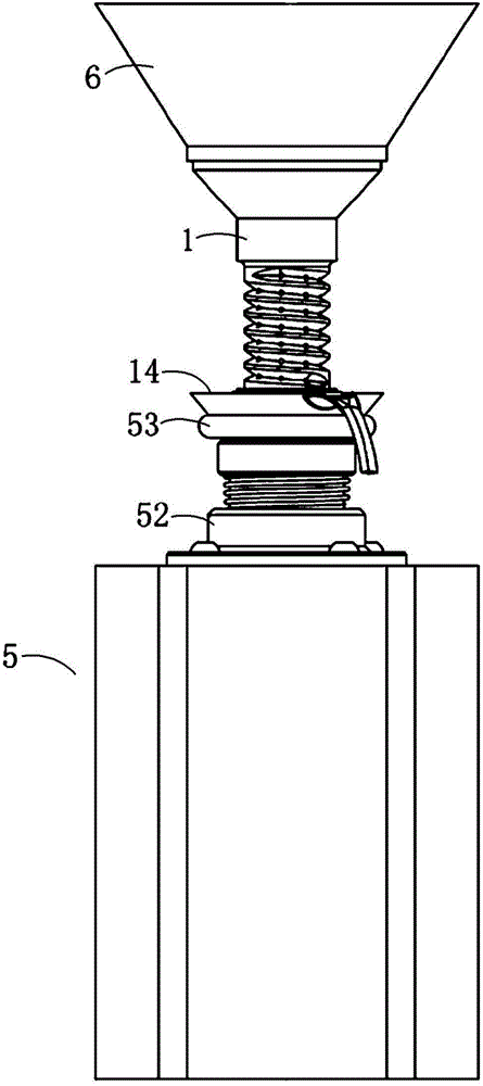
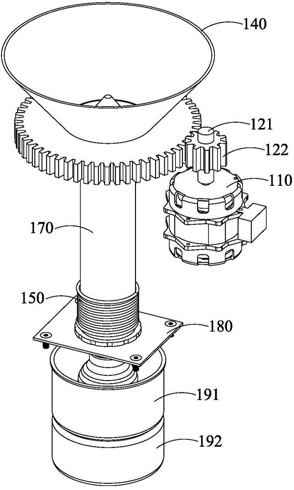
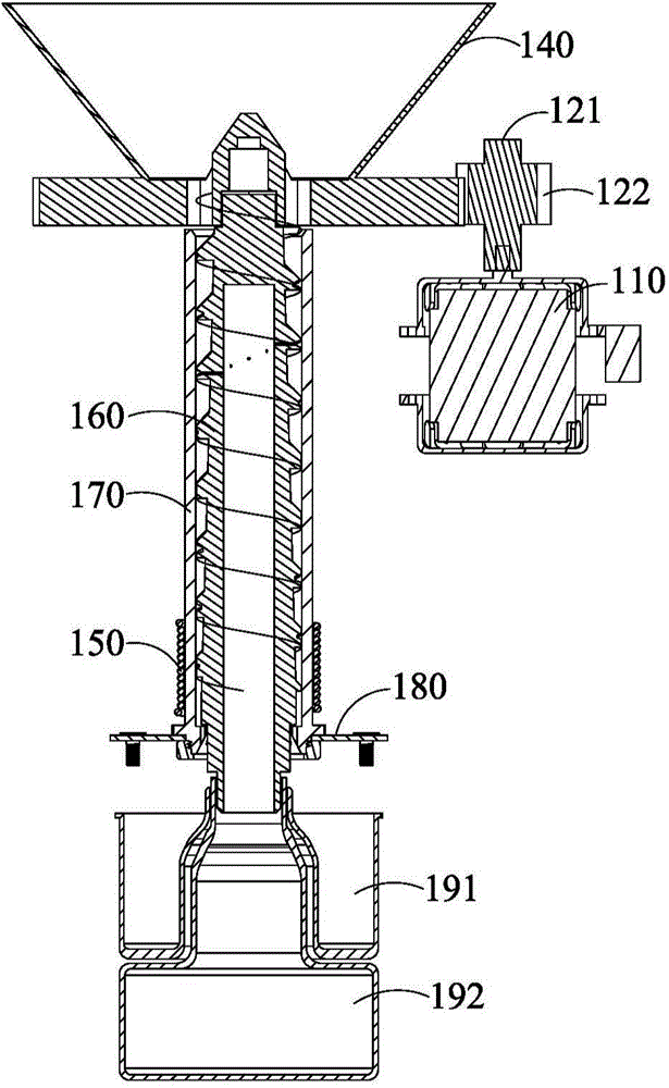
[0058] The oil press of this embodiment is an oil press that drives a screw shaft to rotate oil, such as Figure 2A with 2BAs shown, the oil press includes a driving mechanism, a screw shaft 160, a pressing sleeve 170, a feed hopper 140, a heating pipe 150, a gear plate 130, a bracket 180, an oil collecting bottle 192 and a slag collecting pan 191. The screw shaft 160 is rotatably assembled in the press sleeve 170, the space between the press sleeves 170 forms a press chamber, the open space where the press sleeve 170, the screw shaft 160 and the feed hopper 140 cooperate forms a feeding section, the press sleeve 170 and the screw The cooperating closed cavity of the shaft 160 forms the upper part of the conveyor belt and the lower part of the press section. The conveying section accepts the oil at the feeding port, conveys and pre-presses the oil, and the oil in this section does not melt during pressing; from the beginning of melting during pressing to the slag discharge en...
Embodiment 2
[0069] The oil press of this embodiment is an oil press that drives the press cover to rotate oil, see Figure 10 As shown, the oil press includes a driving mechanism, a pressing rod 360 , a screw pressing sleeve 370 matched therewith, a feeding hopper 340 and a worm wheel 330 . The squeeze rod 360 is rotatably assembled in the squeeze sleeve 370, and the space in the squeeze sleeve 370 forms a squeeze chamber. The open space where the screw press sleeve 370, the press rod 360 and the feed hopper 340 cooperate forms the feeding section, and the closed cavity where the screw press sleeve 370 cooperates with the press rod 360 forms the upper conveyor belt and the lower press section. The conveying section accepts the oil at the feeding port, conveys and pre-presses the oil, and the oil in this section does not melt during pressing; from the beginning of melting during pressing to the slag discharge end is the pressing section, which is used to press the oil to produce oil. The ...
Embodiment 3
[0087]The oil press of this implementation can be a double pusher, that is, the screw shaft and the screw press sleeve push materials simultaneously. A gear can be arranged between the screw shaft and the screw press sleeve, and the gear cooperates with the teeth on the bottom of the screw shaft and the screw press sleeve to realize the simultaneous rotation of the screw shaft and the screw press sleeve. The driving mechanism can be connected with one of the screw shaft and the screw press sleeve, so that the screw shaft and the screw press sleeve can be driven simultaneously. It is also possible to set driving mechanisms for the screw shaft and the screw press sleeve respectively, and the two drive mechanisms drive the screw shaft and the screw press sleeve respectively. When two driving mechanisms are used to respectively drive the screw shaft and the screw press sleeve, there is no need to arrange gears between the screw shaft and the screw press sleeve. When the screw sha...
PUM
 Abstract
Description
Claims
Application Information
 - R&D
- Intellectual Property
- Life Sciences
- Materials
- Tech Scout
- Unparalleled Data Quality
- Higher Quality Content
- 60% Fewer Hallucinations
Browse by: Latest US Patents, China's latest patents, Technical Efficacy Thesaurus, Application Domain, Technology Topic, Popular Technical Reports.
© 2025 PatSnap. All rights reserved.Legal|Privacy policy|Modern Slavery Act Transparency Statement|Sitemap|About US| Contact US: help@patsnap.com