
Expansion tank mounting structure of hybrid electric vehicle

A technology for hybrid electric vehicles and installation structures, which is applied to the power unit, the arrangement of the cooling combination of the power unit, and vehicle components, etc., and can solve problems such as unsatisfactory fixing effects, modal test characteristics, strength and space layout that cannot meet the requirements, etc. , to achieve the effect of ideal fixing effect, enhanced strength and rigidity, and firm connection

Active Publication Date: 2015-06-10
ZHEJIANG GEELY AUTOMOBILE RES INST CO LTD +1
View PDF7 Cites 2 Cited by
  • Summary
  • Abstract
  • Description
  • Claims
  • Application Information

AI Technical Summary

Problems solved by technology

[0003] The purpose of the present invention is to provide an engine expansion tank in order to overcome the disadvantages that the engine expansion tank and the PEU expansion tank are respectively fixed by traditional fixing brackets, the modal test characteristics, strength and space layout cannot meet the requirements, and the fixing effect is not ideal. After installation with the PEU expansion tank, the modal test characteristics, strength and space layout can meet the requirements, and the installation structure of the hybrid vehicle expansion tank with ideal fixing effect

Method used


Image

  • Expansion tank mounting structure of hybrid electric vehicle
  • Expansion tank mounting structure of hybrid electric vehicle
  • Expansion tank mounting structure of hybrid electric vehicle

Examples


Embodiment Construction

[0017] The present invention will be further described below in conjunction with the accompanying drawings.

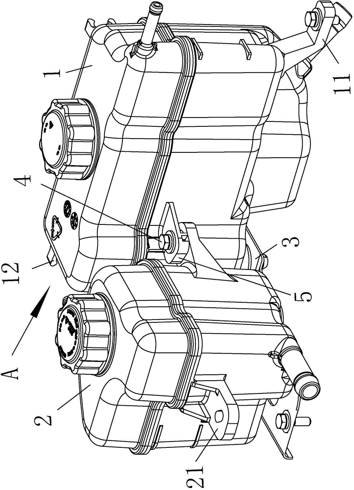
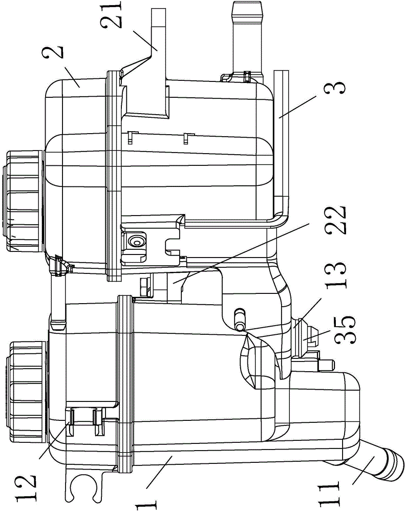
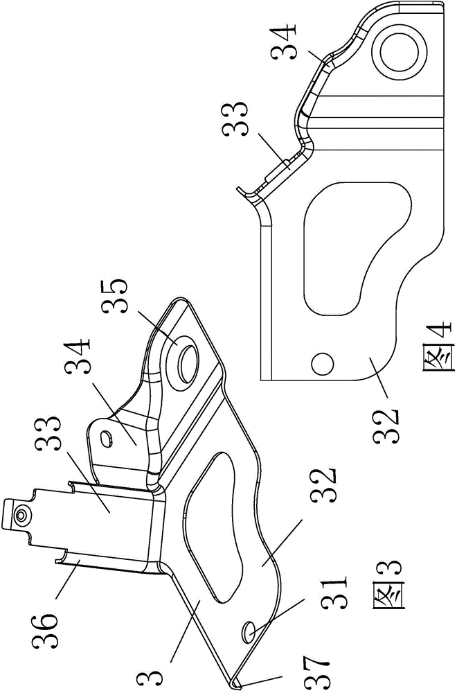
[0018] as attached figure 1 to attach Figure 4 Shown: a hybrid vehicle expansion tank installation structure, including an engine expansion tank 1 with a lower fixing ear 11 at the lower part of the front end and a fixing block 12 at one side and a rear end, a PEU expansion tank 2, and a fixing bracket 3; The PEU expansion tank 2 is arranged in an L shape with the engine expansion tank 1, and one side of the PEU expansion tank 2 is opposite to the rear of the other side of the engine expansion tank 1; the other side of the PEU expansion tank 2 is provided with a side The fixed ear 21; the front end of the PEU expansion tank 2 and the other side end of the engine expansion tank 1 are each provided with a connecting ear 5 connected by a connecting bolt 4; the fixed bracket 3 includes a bottom mounting hole 31 and is connected to the engine expansion tank 1 Bottom plat...


PUM


Abstract

The invention relates to the field of automobile power devices, and aims to provide an expansion tank mounting structure of a hybrid electric vehicle. The expansion tank mounting structure of the hybrid electric vehicle comprises an engine expansion tank, a PEU (power electronic unit) expansion tank and a fixing bracket, wherein one side end of the PEU expansion tank is opposite to the rear part of one side end of the engine expansion tank; engaging lugs connected through connecting bolts are arranged at the front end of the PEU expansion tank and the other side end of the engine expansion tank respectively; the fixing bracket comprises a bottom plate, a vertical plate and a reinforcing plate, and the bottom plate is provided with a bottom mounting hole and connected with the lower end of the engine expansion tank and the lower end of the PEU expansion tank; the upper end of the vertical plate is connected with the rear end of the PEU expansion tank through a screw; the reinforcing plate is connected with the rear end of the engine expansion tank through a screw. According to the expansion tank mounting structure of the hybrid electric vehicle, after the engine expansion tank and the PEU expansion tank are mounted, the modal testing character, strength and spatial arrangement can meet requirements, and the fixing effect is ideal.

Description

technical field [0001] The invention relates to the field of cooling of automobile power devices, in particular to an installation structure of an expansion tank of a hybrid electric automobile. Background technique [0002] The expansion tank is used in the system to buffer pressure fluctuations and part of the water supply. In the thermal system, it is mainly used to absorb the volume of the working medium due to temperature changes; The nitrogen in the tank is compressed. According to Boyle's gas law, the volume of the gas becomes smaller after being compressed and the pressure increases until the pressure of the gas in the expansion tank reaches the same pressure as the water. When the pressure of the gas in the expansion tank reaches the same level, the water is stopped; when the water is lost, the pressure is reduced and the pressure is reduced. The gas pressure in the tank is greater than the water pressure. At this time, the gas expands and squeezes out the water in ...

Claims


Application Information

Patent Timeline
Patent Type & Authority Applications(China)
IPC IPC(8): B60K11/02
Inventor 石振朱启维汤小生谢世斌吴成明冯擎峰
Owner ZHEJIANG GEELY AUTOMOBILE RES INST CO LTD
Learn More