
Installation method of flash smelting furnace

A technology for flash smelting furnaces and installation methods, applied in furnaces, electric furnaces, rotary drum furnaces, etc., can solve the problems of small furnace installation space, difficult construction and high technical requirements, small furnace construction space, etc. The effect of cycle reduction, reasonable design of manufacturing steps, and reduction of construction costs

Active Publication Date: 2017-02-01
MCC5 GROUP SHANGHAI CORPORATION LIMITED
View PDF4 Cites 0 Cited by
  • Summary
  • Abstract
  • Description
  • Claims
  • Application Information

AI Technical Summary

Problems solved by technology

Generally speaking, the flash smelting furnace equipment has a complex structure, many parts, high installation accuracy requirements, and difficult control during installation, and the construction of the furnace body cannot affect the construction of the plant frame. Therefore, the plant frame has been constructed during the furnace body construction, and the furnace body construction Small space, large amount of installation, difficult construction and high technical requirements
[0004] According to the original design drawings and the overall project progress of the main smelting plant, the installation space of the furnace body is small, there are many parts and components, and the requirements for expansion are high. The overall project schedule is very tight. The known traditional hoisting machinery installation is expensive, long construction period, and affected by the structure of the plant, the operating range is small, the precision control error is large
[0005] Therefore there is above-mentioned inconvenience and problem in known smelting furnace installation method

Method used


Image

  • Installation method of flash smelting furnace
  • Installation method of flash smelting furnace
  • Installation method of flash smelting furnace

Examples


Embodiment 1

[0047] The optimization flash smelting furnace installation method of the present invention comprises the following steps:

[0048] a. Set up the flash smelting furnace body installation preparation device, including the following steps:

[0049] see now Figure 9 and 10 , Figure 9 For the flash smelting furnace of the embodiment of the present invention, a 9.7m beam bottom lifting measure transportation layout diagram is installed, Figure 10 for Figure 9 A-A sectional view in .

[0050](1) Set up an electric hoist track beam at an elevation of ▽±9.7m above the main smelting workshop (line 14-15) and install two 10t electric hoists. The electric hoist beam is made of I-beam 360*140*14mm, The track beam adopts [160*65*8.5mm butt-welded square pipes, which are respectively welded and hung with the structural beams of the workshop;

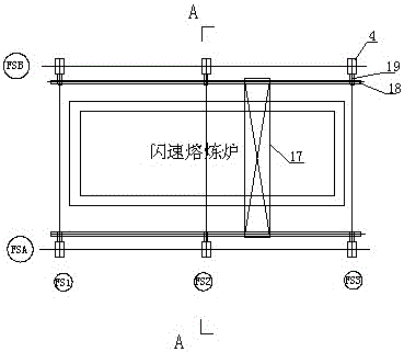
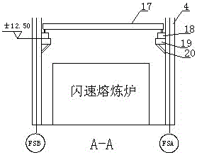
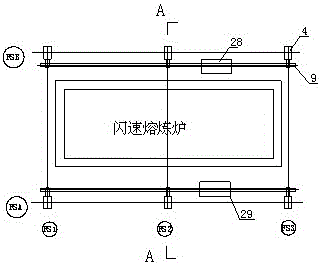
[0051] see now figure 1 and 2 , figure 1 It is the furnace top layout diagram of the flash smelting furnace furnace body and the sedimen...


PUM


Abstract

The invention discloses an optimized flash smelting furnace mounting method which is characterized by comprising the following steps: (a), arranging a furnace body installation and preparation device of a flash smelting furnace; (b), mounting an auxiliary steel platform and a vertical longitudinal beam of the furnace body; (c) transferring various members into the furnace body; (d) mounting a furnace body bottom beam system, an upright post, a straining beam and a furnace bottom cooling system; (e), mounting a reaction tower and an uptake flue layer by layer; and (f) lifting a steel shell on the upper part of the reaction tower. The optimized flash smelting furnace mounting method disclosed by the invention has the advantages that the manufacturing steps are reasonable in design and simple in operation, the control precision is greatly improved, the construction operation cycle is greatly reduced, the engineering construction cost is reduced.

Description

technical field [0001] The invention relates to a method for installing a smelting furnace, in particular to a method for installing a flash smelting furnace which improves the installation accuracy and shortens the construction period. Background technique [0002] The smelting operation is an indispensable operation in the pyrometallurgical copper smelting process. The dry concentrate is sprayed into the reaction space of the flash furnace, so that the concentrate ions are suspended in the high-temperature oxidizing air flow, and the oxidation reaction of sulfide minerals occurs rapidly by using oxygen-enriched air. , and release a lot of heat to form copper matte. At present, with the rapid development of the national economy, the process of industrialization has been significantly accelerated, especially the proportion of heavy industrial projects in national construction has increased year by year. In many fields such as heavy industrial projects, according to the need...

Claims


Application Information

Patent Timeline
Patent Type & Authority Patents(China)
IPC IPC(8): C22B15/00
Inventor 高文建聂丁未卓望雍代文唐益辉代克维
Owner MCC5 GROUP SHANGHAI CORPORATION LIMITED
Learn More