Door shaft driving device of gate

A drive device and door shaft technology, which is applied to roads, restricted traffic, roads, etc., can solve the problems of easy wear and jam, unreasonable structure of the door shaft drive device, etc., and achieves easy disassembly, simple structure, and convenient disassembly and assembly. Effect

Active Publication Date: 2015-06-10
广东同盛联合信息技术有限公司
View PDF7 Cites 10 Cited by
  • Summary
  • Abstract
  • Description
  • Claims
  • Application Information

AI Technical Summary

Problems solved by technology

[0006] Aiming at the unreasonable structure of the door shaft driving device in the prior art, which is easy to be worn and stuck, the present invention provides a door shaft driving device o

Method used


Image

  • Door shaft driving device of gate
  • Door shaft driving device of gate
  • Door shaft driving device of gate

Examples


Embodiment 1

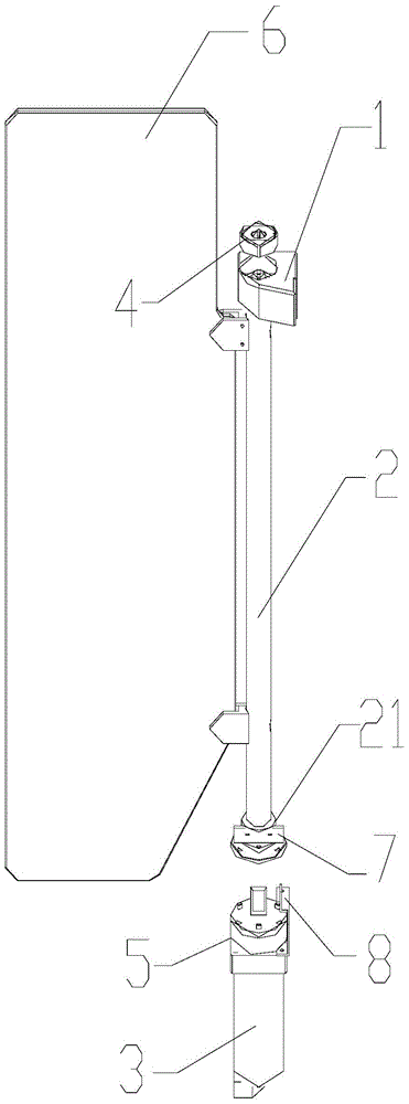
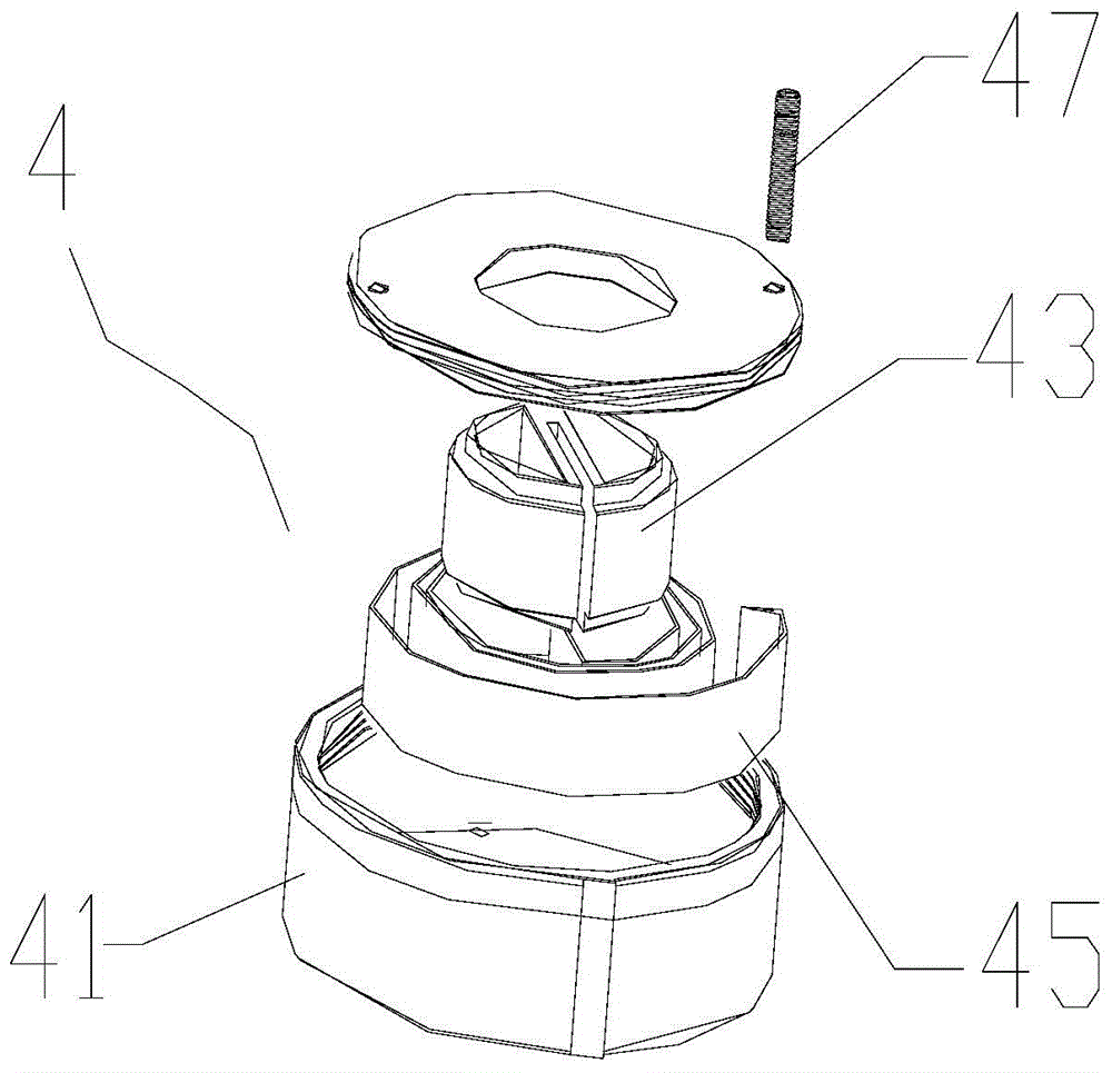
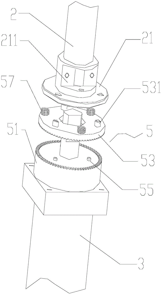
[0031] see figure 1 , figure 2 , a door shaft driving device of a gate machine, comprising a controller and a frame, the frame is provided with a fixing seat 1, and a gate rotating shaft 2 is sleeved on the fixing seat 1, and the gate rotating shaft 2 is connected to the drive The motor 3 is linked; a revolving mechanism 4 is also provided, and the revolving mechanism 4 includes a revolving box 41, a revolving shaft 43 and a torsion shrapnel 45;

[0032] The swivel box 41 is a hollow structure, the swivel box 41 is fixedly installed on the fixed seat 1, the swivel box 41 is sleeved on the gate shaft 2 and can rotate relatively;

[0033] The swivel shaft 43 is arranged in the middle of the inner cavity of the swivel box 41 , and the swivel shaft 43 is fixedly connected with the gate shaft 2 ; the swivel shaft 43 is connected with the end of the gate shaft 3 .

[0034] The torsion elastic piece 45 is arranged on the peripheral side of the swivel shaft 43 , one end of which is...

Embodiment 2

[0052] see Figure 4 , Figure 5 , the present embodiment is an improvement made on the basis of the first embodiment. Compared with the first embodiment, the difference lies in that the swing mechanism 4 in the first embodiment is arranged at the end of the gate shaft 2, and this In the embodiment, the swing mechanism 4 is arranged in the middle of the gate rotating shaft 2 . When the revolving mechanism 4 is arranged in the middle of the gate rotating shaft 2, the revolving shaft 43 is a hollow structure, and the revolving shaft 43 is sleeved on the gate rotating shaft 2 and fixed with a fixing device 47, and the The side wall of the gate shaft 2 is provided with a keyway matching the fixed key 47 .


PUM


Abstract

The invention discloses a door shaft driving device of a gate. The door shaft driving device comprises a controller and a rack, wherein a fixing base is arranged on the rack; a gate rotation shaft is mounted on the fixing base in a sleeving manner and is linked to a driving motor; a swiveling mechanism is further arranged on the rack, and comprises a swiveling box, a swiveling shaft and a torsion spring piece; the swiveling box is a hollow structure, is fixedly installed on the fixing base, and is arranged on the gate rotation shaft in a sleeving manner and can rotate relatively; the swiveling shaft is arranged in the middle of an inner cavity of the swiveling box and is fixedly connected with the gate rotation shaft; the torsion spring piece is arranged on the peripheral side of the swiveling shaft; one end of the torsion spring piece is fixed on the inner wall of the swiveling box, and the other end of the torsion spring piece is fixed on the swiveling shaft. The door shaft driving device is more reasonable in structure, convenient in assembly and lower in failure rate.

Description

technical field [0001] The invention relates to a gate, in particular to a gate driving device of the gate. Background technique [0002] The gate is a channel blocking device (channel management equipment) used to manage the flow of people and regulate the entry and exit of pedestrians. Its most basic and core function is to realize the entrance and exit of only one person at a time, which can be used in various occasions. At present, it is widely used in customs, office buildings, shopping malls, supermarkets, scenic spots and even high-end residential areas. The door shaft driving device is an important part of the gate machine, which controls the opening and closing of the gate. Usually, the door shaft driving device has to complete a large number of switching actions every day, and it also needs to deal with various emergencies such as power failure and collision. Therefore, the door shaft driving device is a vulnerable part of the gate machine. Whether the operation ...

Claims


Application Information

Patent Timeline
IPC IPC(8): E01F13/04
CPCE01F13/06
Inventor 陈伟宏黄皓贤
Owner 广东同盛联合信息技术有限公司
Why Eureka
Try Eureka