
Intelligent explosion-proof solenoid valve

A solenoid valve, intelligent technology, applied in the valve details, valve device, valve shell structure and other directions, can solve the problem of losing the remote or automatic control valve of the cut-off valve, no control mechanism, wasting air source, etc., to improve the control reliability, The effect of preventing freezing blockage and avoiding stagnation or accumulation of water

Active Publication Date: 2015-06-10
CHINA UNIV OF PETROLEUM (BEIJING) +1
View PDF10 Cites 4 Cited by
  • Summary
  • Abstract
  • Description
  • Claims
  • Application Information

AI Technical Summary

Problems solved by technology

Adopting this scheme will cause a lot of safety hazards while wasting gas sources, polluting the environment, and increasing workload, especially for high-sulfur wells
In addition, under the low temperature conditions in winter, the phenomenon of freezing and blocking of traditional solenoid valves occurs frequently, and the shut-off valves produced by various manufacturers cannot completely solve the problems of freezing and blocking in winter; at present, the solenoid valves of various wellhead manufacturers have to rely on the wellhead remote transmission control system Without its own independent control mechanism, in case of continuous rainy weather or power feed caused by control system failure, remote operation will not be possible, and the effect of remote or automatic control of the shut-off valve will be lost.

Method used


Image

  • Intelligent explosion-proof solenoid valve
  • Intelligent explosion-proof solenoid valve

Examples


Embodiment Construction

[0018] In order to have a clearer understanding of the technical features, purposes and effects of the present invention, the specific implementation manners of the present invention will now be described with reference to the accompanying drawings.

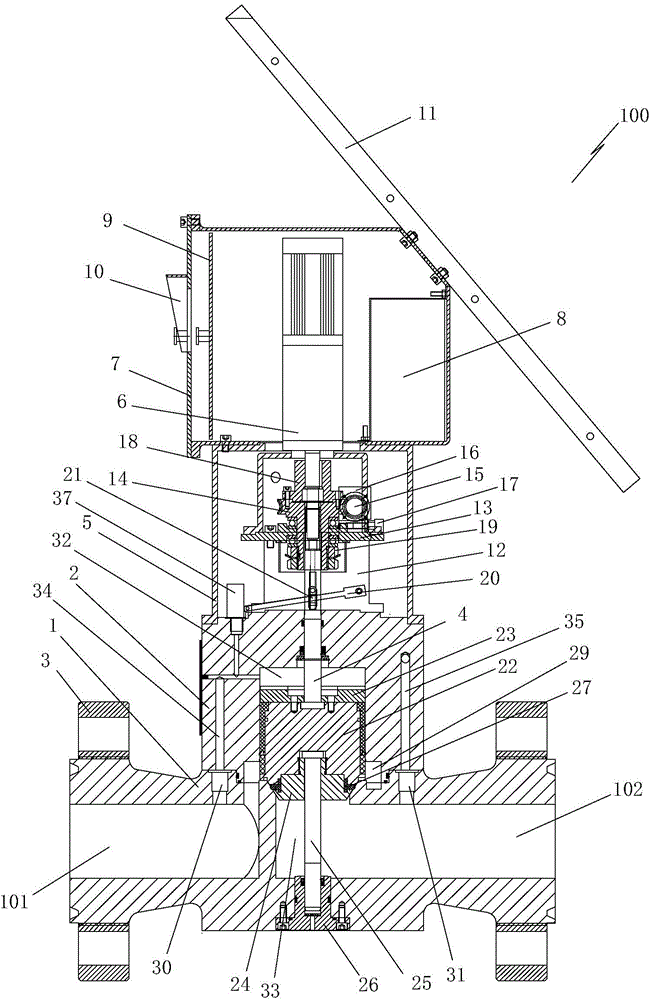
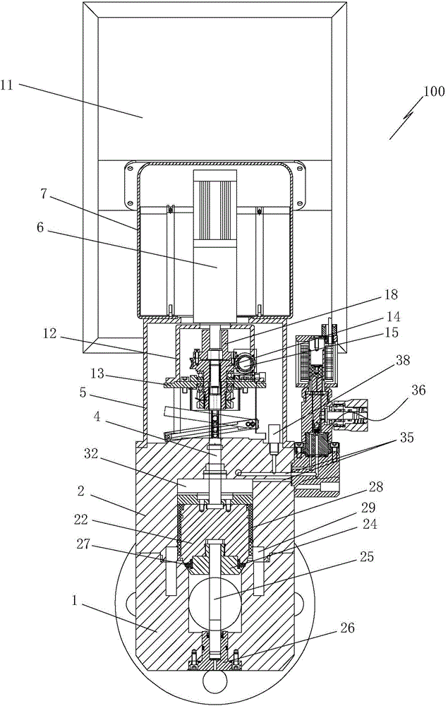
[0019] Such as figure 1 and figure 2 As shown, the present invention provides an intelligent explosion-proof solenoid valve 100, which includes a valve body 1 and a valve cover 2 arranged above the valve body 1. An air inlet passage 101 and an air outlet passage 102 are horizontally provided in the valve body 1. The inlet channel 101 and the outlet channel 102 at both ends of the valve body 1 are respectively connected to the upstream and downstream pipelines through the flange 3 . A main valve core assembly (i.e. a cut-off device) is arranged inside the valve cover 2, the upper end of the main valve core assembly is connected to a valve core lifting mechanism through a pull rod 4, the lower end of the pull rod 4 is fixed on th...


PUM


Abstract

The invention provides an intelligent explosion-proof solenoid valve. The intelligent explosion-proof solenoid valve comprises a valve body and a valve cover, wherein the valve body is internally provided with an air inlet channel and an air outlet channel; a main valve element assembly is arranged in the valve cover; the upper end of the main valve element assembly is connected with a valve element lifting mechanism by a pull rod; the lower end of the pull rod is fixedly arranged at the upper end of the main valve element assembly; the upper end of the pull rod upwards stretches out of the top of the valve cover and is connected with the valve element lifting mechanism. The valve element lifting mechanism is arranged in a shield and the shield is fixedly arranged at the top of the valve cover; a motor which is vertically arranged in arranged above the shield; the output shaft of the motor is connected with the valve element lifting mechanism; the motor is located in a control cabinet; the control cabinet is fixed above the shield; a lithium battery and a control panel are further arranged in the control cabinet; a display screen is arranged on the side wall of the control cabinet; a solar panel for charging the lithium battery is arranged on the outer side of the control cabinet. The intelligent explosion-proof solenoid valve can be used for independently finishing the control of switching on and off the valve in the field, and other existing equipment on a wellhead is not needed; the control reliability is improved.

Description

technical field [0001] The invention relates to a valve used for the wellhead of a gas well, in particular to an intelligent explosion-proof electromagnetic valve. Background technique [0002] With the vigorous promotion and application of natural gas in my country, solenoid valves are widely used in gas wells as safety shut-off valves. However, the opening height of the spool of the traditional solenoid valve is limited, and throttling often occurs, which affects the production efficiency of the gas well. At present, the opening height of the main valve core of the solenoid valve is increased by means of evacuation, that is, the opening of the on-site shut-off valve is usually in the form of evacuation, and the gas in the upper chamber is directly discharged to the outside. Adopting this scheme will cause a lot of potential safety hazards while wasting gas sources, polluting the environment, and increasing the workload, especially for wells with high sulfur content. In a...

Claims


Application Information

Patent Timeline
IPC IPC(8): E21B34/02F16K31/05F16K31/06F16K31/53F16K37/00F16K27/00
CPCE21B34/02F16K27/029F16K31/05F16K31/0655F16K31/53F16K37/0091
Inventor 刘广峰顾岱鸿魏会军王娟成鹏机张帆孙钢峰
Owner CHINA UNIV OF PETROLEUM (BEIJING)
Learn More