Microfluidic Flow Regulator Based on Pneumatic Drive

A flow regulating device and pneumatic drive technology, applied in the field of microfluidics, can solve the problems of unmeasured actual flow, low flow regulation accuracy, and slow dynamic response speed, etc., and achieve good dynamic regulation characteristics, fast dynamic response speed, and flow regulation accuracy high effect

Active Publication Date: 2017-08-04
HARBIN INST OF TECH
View PDF5 Cites 1 Cited by
  • Summary
  • Abstract
  • Description
  • Claims
  • Application Information

AI Technical Summary

Problems solved by technology

[0003] The purpose of the present invention is to solve the problems of low flow regulation accuracy, slow dynamic response speed and unmeasurable actual flow rate when using a syringe pump to adjust the flow rate in the microfluidic system, and provides a microfluidic flow rate regulator based on air pressure drive

Method used


Image

  • Microfluidic Flow Regulator Based on Pneumatic Drive
  • Microfluidic Flow Regulator Based on Pneumatic Drive
  • Microfluidic Flow Regulator Based on Pneumatic Drive

Examples


specific Embodiment approach 1

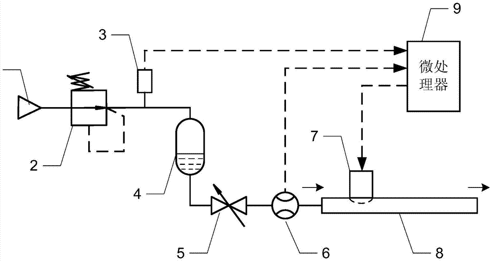
[0011] Specific implementation mode one: the following combination figure 1 with figure 2 Describe this embodiment, the air pressure-driven microfluid flow adjustment device described in this embodiment includes an air supply source 1, a pressure reducing valve 2, a pressure sensor 3, a liquid container 4, a valve 5, a flow meter 6, and a microvalve 7. The liquid microchannel 8 and the microprocessor 9; the gas inlet of the pressure reducing valve 2 communicates with the compressed air outlet of the gas supply source 1; the gas outlet of the pressure reducing valve 2 communicates with the gas inlet of the liquid container 4, and the liquid container The liquid outlet of 4 communicates with the inlet of the valve 5, and the outlet of the valve 5 communicates with the inlet of the liquid microchannel 8 through the flow meter 6; the microvalve 7 is embedded in the liquid microchannel 8;

[0012] The pressure sensor 3 detects the outlet gas pressure of the pressure reducing valv...

specific Embodiment approach 2

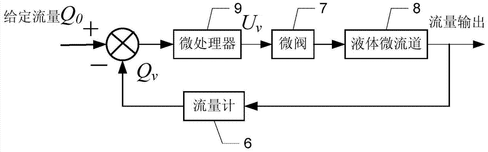
[0016] Specific implementation mode two: the following combination figure 2 Describe this embodiment, this embodiment will further explain Embodiment 1, the formation process of the flow control command signal of the microprocessor 9 is: the microprocessor 9 according to the given flow signal Q 0 and the actual liquid flow signal Q collected by flowmeter 6 v The difference forms the flow control command signal U v . The microprocessor 9 gives a flow control instruction signal to change the working state of the microvalve 7, and then change the flow cross section of the liquid microchannel 8, so that the actual liquid flow signal Q v with a given flow signal Q 0 Tend to be consistent, to achieve closed-loop control of flow.

specific Embodiment approach 3

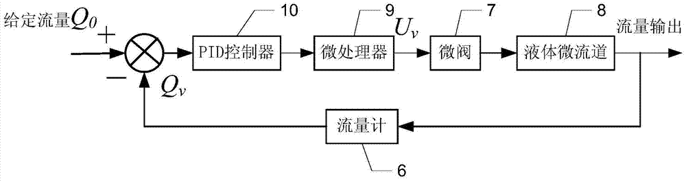
[0017] Specific implementation mode three: the following combination image 3 Describe this embodiment, this embodiment will further explain Embodiment 1 or 2, it also includes PID controller 10, given flow signal Q 0 and the actual liquid flow signal Q collected by flowmeter 6 v The difference is adjusted by the PID controller 10, and the flow control command signal U is formed by the microprocessor 9 v . The difference between the two is processed by the PID microprocessor and then the flow control command signal U is given. v , improve the flow adjustment accuracy and dynamic response speed, and meet the flow adjustment needs of different microfluidic devices.


PUM


Abstract

A microfluidic flow regulating device driven by air pressure belongs to the field of microfluidics. The invention aims to solve the problems of low flow regulation accuracy, slow dynamic response speed and unmeasurable actual flow rate in microfluidic systems when using syringe pumps to regulate flow. The present invention adopts the air pressure drive method, the air supply source provides compressed air, and the outlet pressure is adjusted through the pressure reducing valve to obtain a stable air supply pressure and the pressure is measured by the pressure sensor. The liquid in the liquid container is driven by the air pressure, passes through the valve, The flowmeter enters the liquid microchannel, and the actual liquid flow rate is measured by the flowmeter and fed back to the microprocessor. The microprocessor outputs a control signal to change the working state of the microvalve, adjust the liquid flow rate of the liquid microchannel, and realize the closed-loop control of the flow rate. Further, PID control algorithm can be used to improve the adjustment accuracy and dynamic response speed of the flow rate, and can accurately and quickly adjust the liquid flow rate of the microchannel.

Description

technical field [0001] The invention relates to a microfluid flow regulating device driven by air pressure, which belongs to the field of microfluid. Background technique [0002] Currently, syringe pumps are the most commonly used flow regulating elements in microfluidic systems. Although the working principle of the syringe pump is simple and the price is cheap, there are many shortcomings in regulating the flow of the syringe pump. 1) Low accuracy of flow adjustment: The syringe pump is driven by a stepping motor, and there is mechanical vibration during operation, which causes periodic fluctuations in the flow of the microchannel, especially when adjusting a small flow rate, the amplitude of the flow fluctuation is relatively large. 2) The dynamic response speed of the flow is slow: the flow adjustment speed of the syringe pump is affected by the volume of the syringe. When the flow rate of the microchannel changes, it takes tens of seconds or even hundreds of meters fo...

Claims


Application Information

Patent Timeline
Patent Type & Authority Patents(China)
IPC IPC(8): F17D1/14F17D3/01F17D3/18
Inventor 李松晶曾文佟志忠黄其涛
Owner HARBIN INST OF TECH
Why Eureka
Try Eureka