

Fiber Bragg grating strain-measuring method and fiber Bragg grating strain sensor
A technology of force measuring sensor and fiber grating, which is applied in the direction of measuring force by measuring the change of optical properties of materials when they are stressed, can solve the problems of poor anti-interference, inability to collect data in real time, inaccurate readings, etc., and achieve anti-electromagnetic Interference, accurate force readings, and the effect of automatic measurement
- Summary
- Abstract
- Description
- Claims
- Application Information
AI Technical Summary
Problems solved by technology
Method used
Image

Examples
Embodiment 1
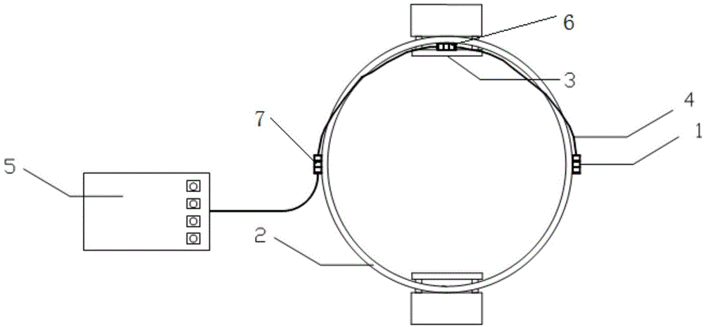
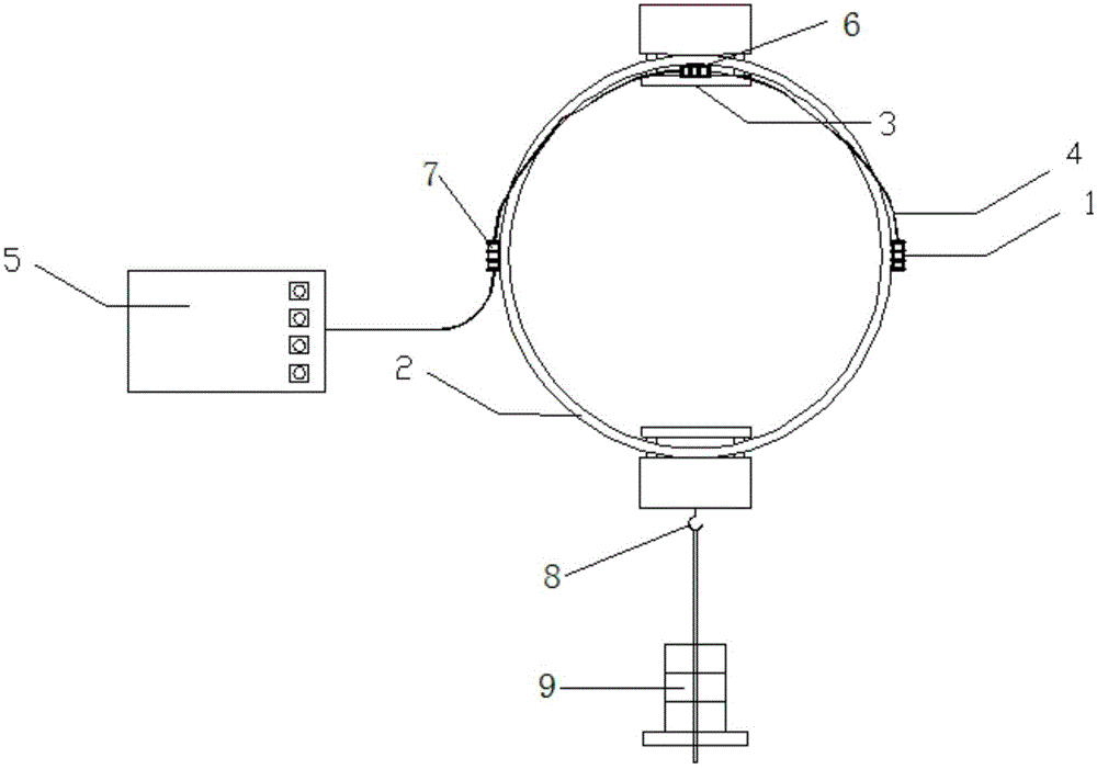
[0022] A fiber grating load cell, comprising three fiber grating sensing modules 1, 6 and 7, a thin-walled ring 2, a temperature compensation block 3, a signal transmission fiber 4 and a fiber grating demodulator 5, the three fiber grating sensors The sensing modules are connected in series with each other through the signal transmission optical fiber 4, and then respectively pasted on the left and right ends of the outer wall of the thin-walled ring 2, and the surface of the temperature compensation block 3 connected to the thin-walled ring 2, and the fiber grating demodulator 5 is connected to the thin-walled ring 2. The third fiber grating sensing modules 7 at the left and right ends of the outer wall are connected through signal transmission fibers. Both the thin-walled ring 2 and the temperature compensation block 3 are made of metal materials. Among the three fiber grating sensing modules, the first fiber grating sensing module 1 and the third fiber grating sensing modul...
PUM
 Abstract
Description
Claims
Application Information