Oil abrasive particle detecting sensor and design method thereof

A technology for detecting sensors and oil abrasive particles, which is applied in the design of oil abrasive particle detection sensors and in the field of oil abrasive particle detection devices, and can solve problems such as difficult to remove noise components

Active Publication Date: 2015-06-10
GUILIN UNIV OF ELECTRONIC TECH
View PDF4 Cites 25 Cited by
  • Summary
  • Abstract
  • Description
  • Claims
  • Application Information

AI Technical Summary

Problems solved by technology

[0007] In addition, the existing detection device for metal abrasive particles in the oil is also difficult to remove the noise component in the processing circuit of the induction coil output signal, so it needs to be improved.

Method used


Image

  • Oil abrasive particle detecting sensor and design method thereof
  • Oil abrasive particle detecting sensor and design method thereof
  • Oil abrasive particle detecting sensor and design method thereof

Examples


Embodiment Construction

[0078] Embodiments of the present invention will be described in further detail below in conjunction with the accompanying drawings.

[0079] Embodiment of the design method of the oil abrasive particle detection sensor

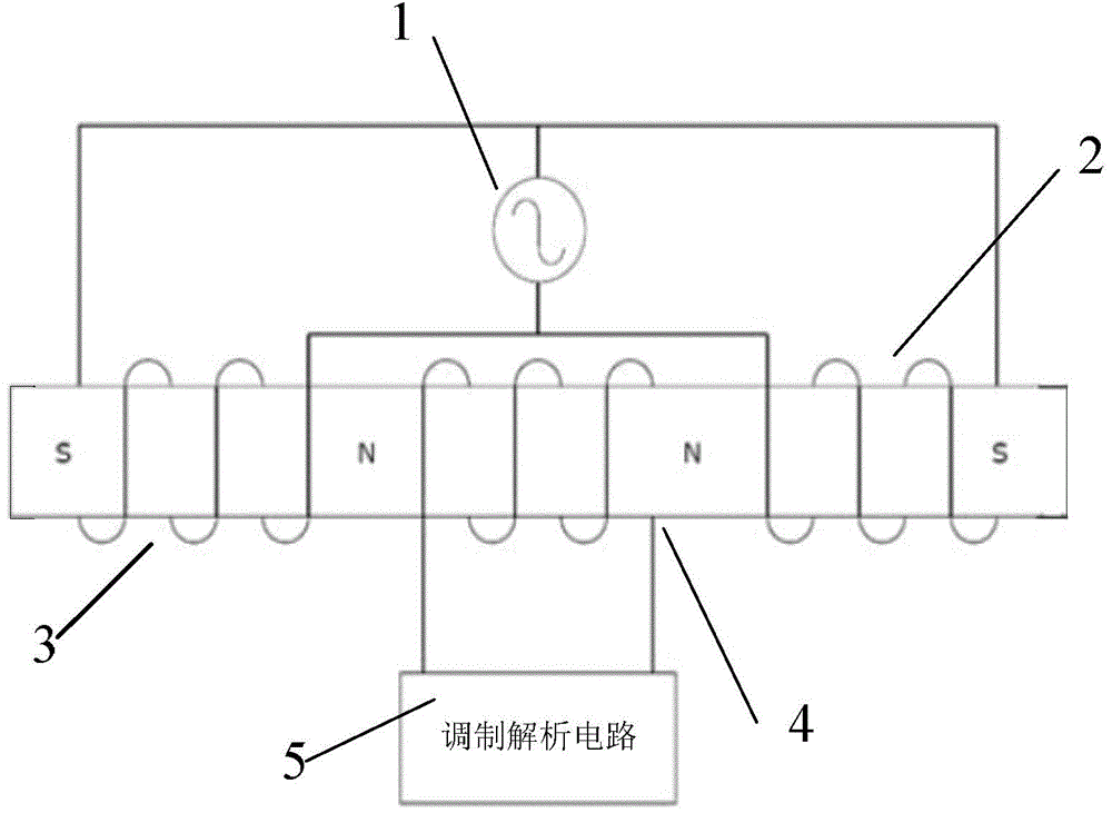
[0080] In this example, the oil wear particle detection sensor is a three-solenoid differential sensor, such as figure 1 As shown, it includes an induction coil 4 with the same center line and two excitation coils 2, 3, the two excitation coils 2, 3 are wound in opposite directions, respectively on the left and right sides of the induction coil 4. Two excitation coils 2 and 3 are connected in parallel with the high-frequency excitation signal source 1, that is, one end of the two excitation coils 2 and 3 close to the induction coil 4 is connected and connected to one end of the high-frequency excitation signal source 1, and the two excitation coils 2 and 3 are The other end is connected to the other end of the high-frequency excitation signal source 1 . The...


PUM

PropertyMeasurementUnit
diameteraaaaaaaaaa
diameteraaaaaaaaaa

Abstract

The invention relates to an oil abrasive particle detecting sensor and a design method thereof. The design method comprises, after a sensor framework is determined, calculating the relation curve between magnetic field intensity B and number of coil turns n by formula, take the n, which corresponds to the maximum value of the B, as the number of turns of an induction coil and two exciting coils. According to the oil abrasive particle detecting sensor, the number of coils of every coil is determined according to the design method; the output end of the induction coil is connected with a modulation and demodulation circuit, which is sequentially connected with a pre-amplification circuit, a low-pass filter, a high-pass filter and an oscilloscope. For signal output components, the oil abrasive particle detecting sensor provides the modulation and demodulation circuit comprising the pre-amplification circuit, the low-pass filter and the high-pass filter. The design method of the oil abrasive particle detecting sensor helps design the number of turns of the induction coil, which can maximize signal output amplitude, and under the dimension of the mass-produced sensor framework, the induction coil can be conveniently mounted on various oil-lubricated engines. The oil abrasive particle detecting sensor can accurately obtain abrasive particle associated information and be applied to measuring metal abrasive particles only with a diameter of 500 mu m.

Description

technical field [0001] The invention belongs to the field of machine state monitoring and fault diagnosis, and in particular relates to a design method of an oil abrasive particle detection sensor and an oil liquid abrasive particle detection device. Background technique [0002] Today's mechanical equipment often has the characteristics of high precision and high speed, but this will bring the hazards of accelerated wear. Mechanical equipment must use lubricating oil to lubricate high-speed rotating parts such as gears and bearings in order to make them operate normally. The good condition of lubricating oil can reduce mechanical wear and effectively extend the service life of equipment. Therefore, the detection of oil is very important. From the detection and analysis of abrasive particles, not only the state of the oil can be obtained, but also the information on the lubrication and wear of the equipment can be obtained, and the oil or related parts can be replaced in tim...

Claims


Application Information

Patent Timeline
Patent Type & Authority Applications(China)
IPC IPC(8): G01N15/00G01N15/02
Inventor 王衍学丁永彬张应红何水龙蒋占四张锁峰董智鹏
Owner GUILIN UNIV OF ELECTRONIC TECH
Why Eureka
Try Eureka