
A microwave step thermal imaging detection and tomography method and system

A tomographic imaging and imaging detection technology, which is applied in the fields of medical imaging, target detection, and non-destructive testing, can solve problems such as inability to characterize tomographic imaging, detection methods relying on thermal images and transient temperature curves, and susceptibility to noise interference

Active Publication Date: 2018-02-23
上海光脉医疗科技有限公司
View PDF3 Cites 0 Cited by
  • Summary
  • Abstract
  • Description
  • Claims
  • Application Information

AI Technical Summary

Problems solved by technology

The existing microwave thermal imaging defect detection technology has the following deficiencies: 1) The defect detection method relies on the original thermal image and transient temperature curve, which is susceptible to noise interference; 2) There is no effective quantitative method for defect depth; 3) It cannot characterize a specific depth Property changes and implementation tomography
The existing microwave thermal imaging target detection technology also has the same deficiencies as those in the fields of non-destructive testing and medical imaging.

Method used


Image

  • A microwave step thermal imaging detection and tomography method and system
  • A microwave step thermal imaging detection and tomography method and system
  • A microwave step thermal imaging detection and tomography method and system

Examples


Embodiment Construction

[0055] Specific embodiments of the present invention will be described below in conjunction with the accompanying drawings, so that those skilled in the art can better understand the present invention.

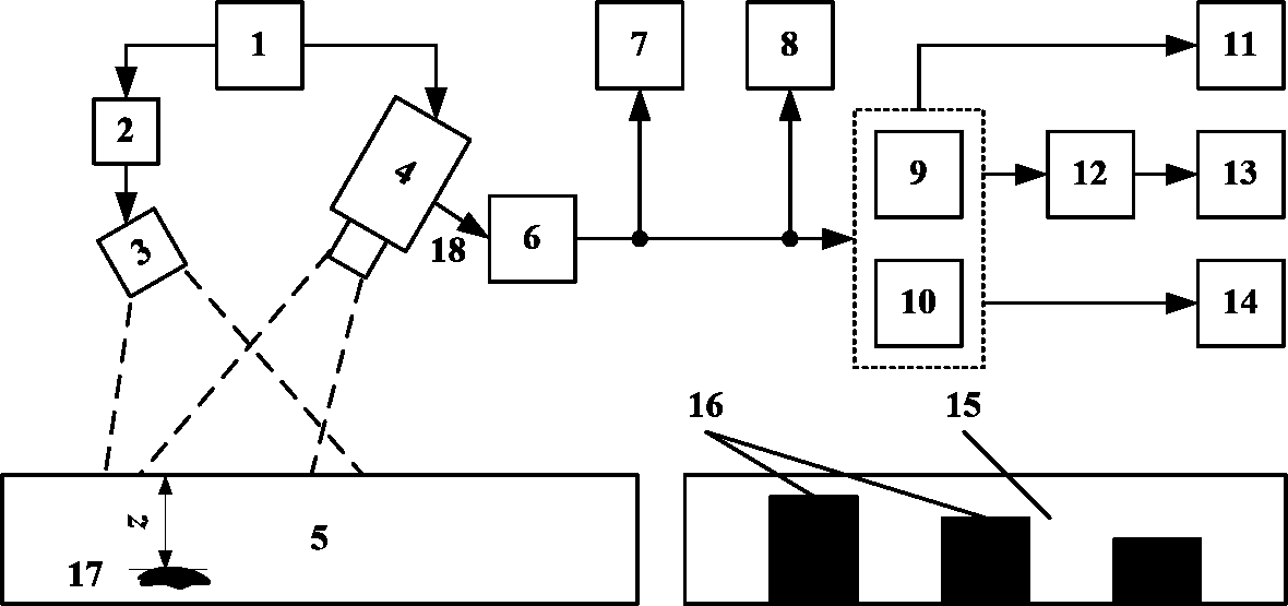
[0056] figure 1 It is a schematic diagram of a microwave step thermal imaging detection and tomography system, which mainly includes: control module 1, microwave generating device 2, antenna 3, thermal imager 4, object to be inspected 5, computer 6, image display module 7, instantaneous State signal module 8, signal processing module 9, differential processing module 10, defect detection module 11, quantitative relationship module 12, defect quantitative module 13, tomographic imaging module 14, standard test piece 15, etc.

[0057] The specific implementation steps of a microwave step thermal imaging detection and tomography method based on a microwave step thermal imaging detection and tomography system are as follows:

[0058] 1) Use the control module 1 to set the system ...


PUM


Abstract

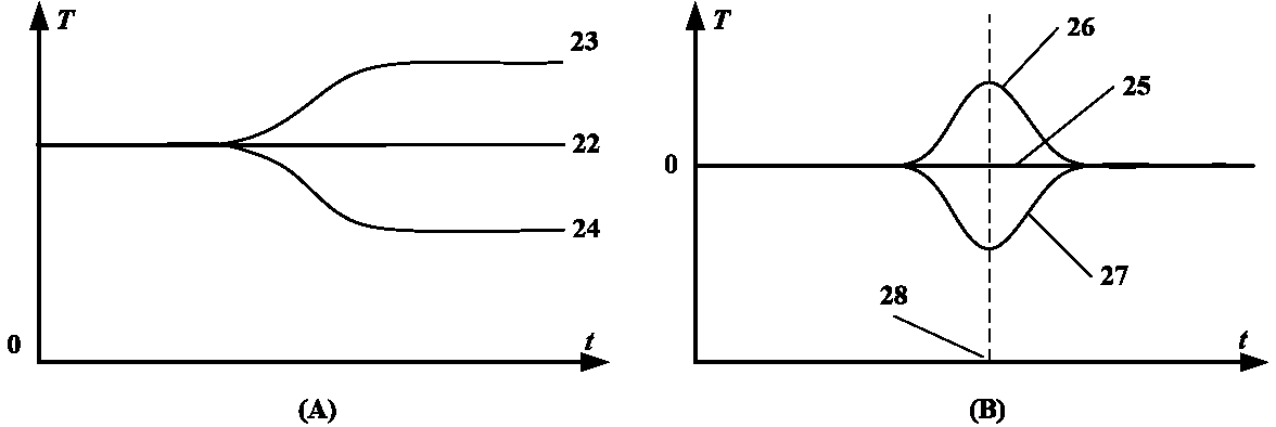
The invention discloses a microwave step thermal imagery detection and tomography method and system. The system is composed of a control module, a microwave generation device, a thermal imager, a computer and a plurality of algorithm modules. The method comprises the steps: heating a detected object by means of microwaves and recording transient temperature signals on the surface of the detected object; calculating a second derivative of the transient temperature signals and extracting a peak time as a characteristic value; utilizing the transient temperature signal in a defect-free area as a reference signal, performing a differential calculation for the transient temperature signal in the detected area and the reference signal to obtain a transient differential signal, extracting a separation time and a maximum-value time as the characteristic values; imaging by utilizing the characteristic values and judging whether a defect exists; establishing a quantitative relation between the characteristic values and the depth by virtue of theoretical analysis and testing, and quantifying the depth of an unknown defect; and realizing tomography in different depth ranges by utilizing a temperature rising rate in different time ranges. The method and the system are applicable to the fields such as nondestructive testing, medical imaging and target detection.

Description

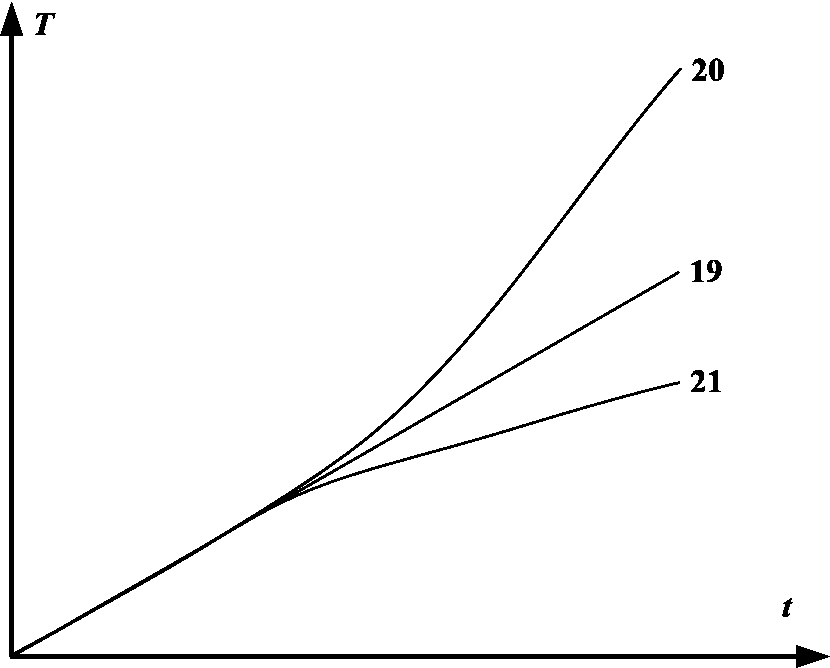
technical field [0001] The invention belongs to the technical fields of non-destructive testing, medical imaging and target detection, and in particular relates to a microwave thermal imaging defect detection, tomography and target detection method and system. Background technique [0002] With the development of modern science and industrial technology, non-destructive testing technology has become a necessary means to ensure product quality and equipment operation safety. At present, representative non-destructive testing technologies mainly include radiographic testing, ultrasonic testing, penetrant testing, magnetic particle testing, eddy current testing, and thermal imaging testing. [0003] Thermal imaging inspection technology uses a heat source to heat the inspected object, and uses a thermal imager to observe and record the temperature change information on the surface of the inspected object, so as to detect and evaluate the surface and internal defects of the insp...

Claims


Application Information

Patent Timeline
Patent Type & Authority Patents(China)
IPC IPC(8): G01N25/72G01N22/02
Inventor 何赟泽杨瑞珍
Owner 上海光脉医疗科技有限公司
Learn More