Solar cell rear passivation method

A solar cell and backside passivation technology, which is applied in the direction of circuits, electrical components, sustainable manufacturing/processing, etc., can solve the problems of restricting production capacity and high cost, and achieve the goals of increasing production capacity, saving the total cost of the process, and reducing costs Effect

Active Publication Date: 2017-01-25
BEIJING NAURA MICROELECTRONICS EQUIP CO LTD
View PDF6 Cites 0 Cited by
  • Summary
  • Abstract
  • Description
  • Claims
  • Application Information

AI Technical Summary

Problems solved by technology

However, although SiN x An increase in the silicon content of the SiN can improve the passivation performance, but the possibility of being eroded by the aluminum paste during the aluminum sintering process on the back is also greater, so SiN with a high silicon content on the back x The thickness generally needs to be greater than 80nm, which also restricts the improvement of production capacity and keeps the cost high

Method used


Image

  • Solar cell rear passivation method
  • Solar cell rear passivation method

Examples


Embodiment Construction

[0029] The specific embodiment of the present invention will be further described in detail below in conjunction with the accompanying drawings.

[0030] It should be noted that, in the following specific embodiments, when describing the embodiments of the present invention in detail, in order to clearly show the structure of the present invention for the convenience of description, the structures in the drawings are not drawn according to the general scale, and are drawn Partial magnification, deformation and simplification are included, therefore, it should be avoided to be interpreted as a limitation of the present invention.

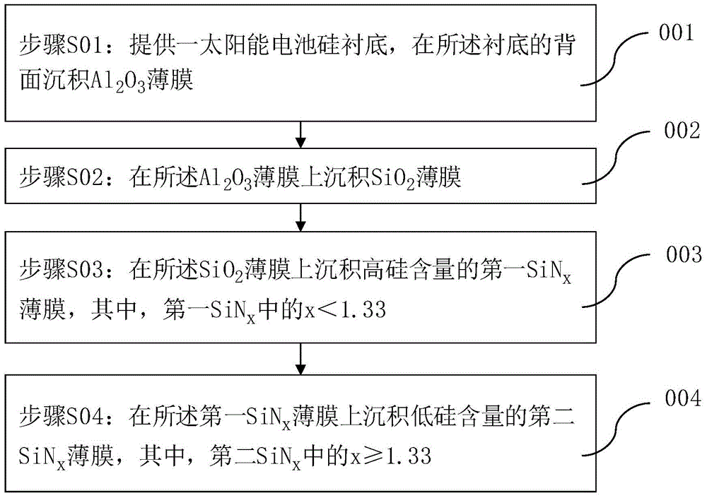
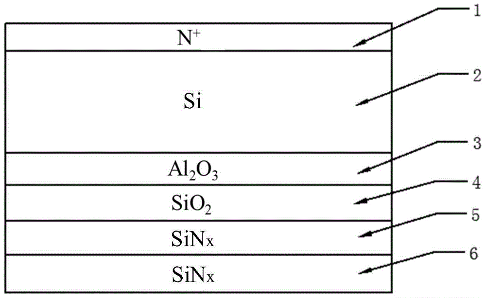
[0031] In the following specific embodiments of the present invention, please refer to figure 1 , figure 1 Is the flow chart of solar cell backside passivation method of the present invention; Meanwhile, please refer to figure 2 , figure 2 is an embodiment of the present invention according to figure 1 Schematic diagram of the structure of the ...


PUM


Abstract

The invention discloses a method for passivating the backside of a solar battery. The backside of the solar battery is passivated by a four-layer laminated passivation film containing Al2O3 / SiO2 / high-silicon SiNx / low-silicon SiNx; the interference of the high-silicon SiNx to fixed positive charges can be effectively eliminated through increasing the deposition of the SiO2 layer, thereby reducing the minimal thickness of the Al2O3. The high-silicon SiNx is able to keep the hydrogen passivation effect to the silicon surface, whereas the erosion to the inner layer of film during the aluminum sintering process can be prevented by utilizing the low-silicon SiNx. Therefore, a significant reduction to the total thickness of the passivation film can be achieved, the productivity can be further increased, the total technology cost can be saved, and the requirements of a mass production can be met.

Description

technical field [0001] The present invention relates to the field of crystalline silicon solar cells, and more specifically, to a back passivation method of solar cells. Background technique [0002] An important direction for the development of high-efficiency solar cells is to adopt double-sided passivation structures, such as P-type substrate PERC (passivated emitter and rear side cell) cells and N-type substrate PERT (passivated emitter and rear total diffused) cells. Due to the existence of the surface state of the silicon wafer, the surface recombination rate is relatively high, which affects the minority carrier (minority carrier) lifetime. The passivation layer can reduce the recombination rate on the surface of the silicon wafer through chemical passivation and field effect passivation. Among them, chemical passivation can reduce the density of various defect states by saturating the dangling bonds on the surface of the silicon wafer, and reduce the surface recombi...

Claims


Application Information

Patent Timeline
Patent Type & Authority Patents(China)
IPC IPC(8): H01L31/0216H01L31/18
CPCY02P70/50
Inventor 张勤杰傅建奇李建国张燕
Owner BEIJING NAURA MICROELECTRONICS EQUIP CO LTD
Why Eureka
Try Eureka