Dedusting and defogging device

A technology of mist removal device and mist eliminator, which is applied in combination devices, dispersed particle separation, chemical instruments and methods, etc., can solve problems such as entry, reduce droplet volume and dust volume, improve dust removal and mist removal capability, reduce Effects of droplet size and particle size

Inactive Publication Date: 2015-06-17
RPT SHANGHAI ENVIRONMENTAL EQUIP
View PDF6 Cites 2 Cited by
  • Summary
  • Abstract
  • Description
  • Claims
  • Application Information

AI Technical Summary

Problems solved by technology

[0003] However, when the dust collector is in operation, a large amount of water needs to be sprayed inside to clean its anode plate and cathode line. At the outlet of the dust collector, there will inevitably be a large number of liquid droplets and fine particles or fine smoke. The air enters the flue at the rear together, and then floats out through the chimney

Method used


Image

  • Dedusting and defogging device
  • Dedusting and defogging device
  • Dedusting and defogging device

Examples


Embodiment Construction

[0026] The invention discloses a dedusting and defogging device, which can reduce the amount of droplets and dust carried in the flue gas.

[0027] The technical solutions in the embodiments of the present invention will be clearly and completely described below with reference to the accompanying drawings in the embodiments of the present invention. Obviously, the described embodiments are only a part of the embodiments of the present invention, but not all of the embodiments. Based on the embodiments of the present invention, all other embodiments obtained by those of ordinary skill in the art without creative efforts shall fall within the protection scope of the present invention.

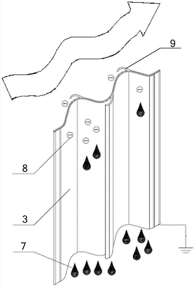
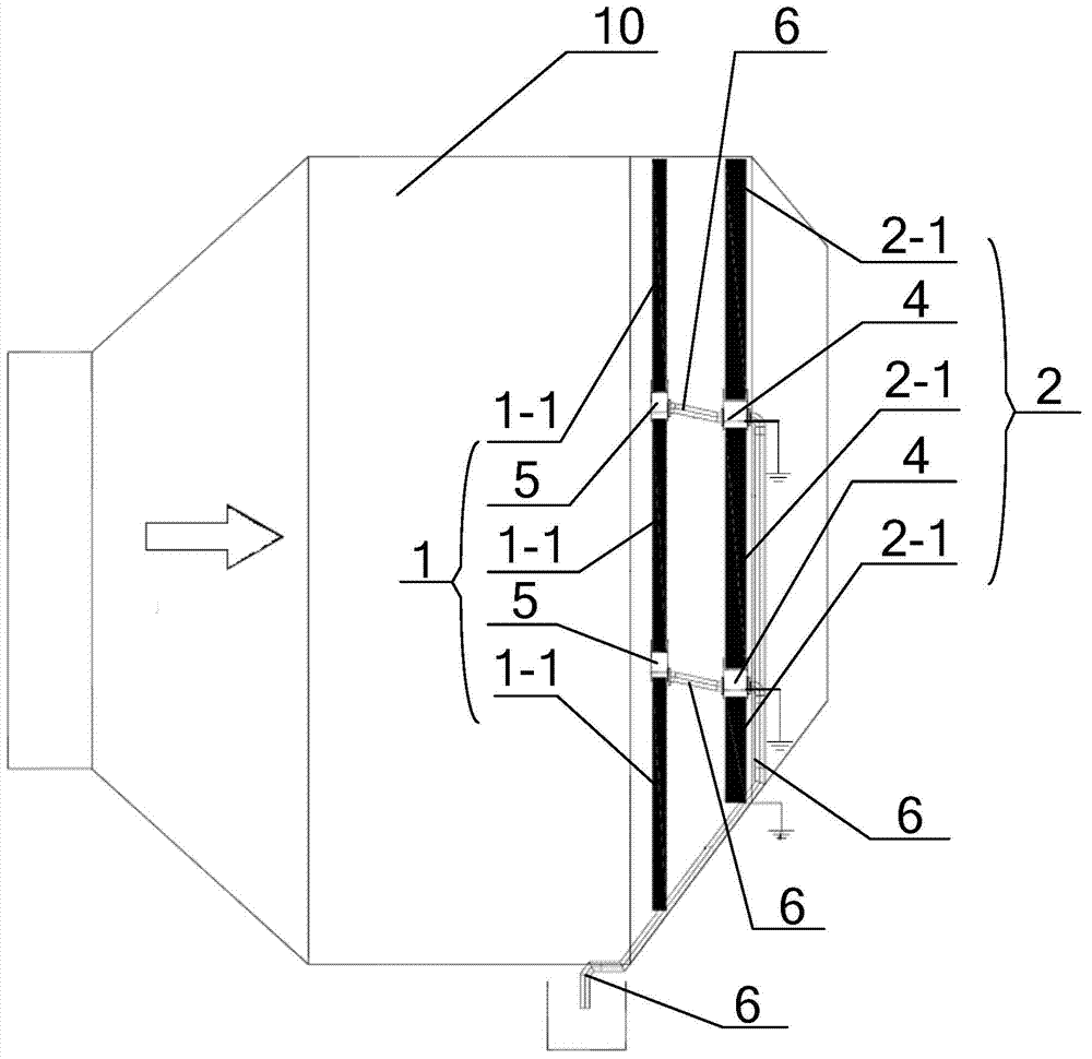
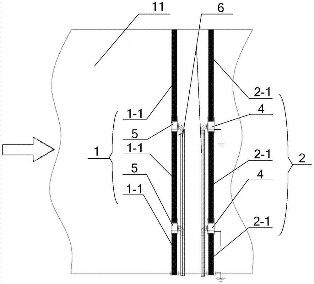
[0028] Please refer to Figure 1 to Figure 3 ,in, figure 1 The schematic diagram of the secondary dust removal and mist eliminator intercepting the droplets and particles in the flue gas in the specific embodiment provided by this application, figure 2 In the specific embodiment provided by th...


PUM


Abstract

The application discloses a dedusting and defogging device which comprises a dedusting and defogging device body, wherein blades of the dedusting and defogging device body are conductive blades, water collecting tanks corresponding to the conductive blades are conductive water collecting tanks; the end parts of the conductive blades are placed in the conductive water collecting tanks; the conductive blades and the conductive water collecting tanks are all grounded. According to a smoke dust purification system and the dedusting and defogging device provided by the invention, liquid drops, small droplets with negative charges and fine particulate matters in flue gas can be intercepted, especially, liquid drops and particles with the size being smaller than 20 microns can be intercepted, so that the amount of droplets and dust carried by the flue gas can be greatly reduced.

Description

technical field [0001] The invention relates to the technical field of flue gas purification devices, in particular to a dust removal and mist removal device. Background technique [0002] With the improvement of environmental protection requirements, the emission requirements of power plant chimneys are also getting higher and higher, and the emission of power plant chimneys needs to meet super clean emission standards. Therefore, in order to further reduce the soot content at the outlet of the absorption tower, a dust collector is usually installed between the outlet of the absorption tower and the chimney, and the dust collector is used to collect fine particles and various dusts in the flue gas. [0003] However, when the dust collector is running, a large amount of water needs to be sprayed inside to clean its anode plate and cathode line. At the outlet of the dust collector, a large number of droplets and fine particles or fine soot will inevitably appear along with th...

Claims


Application Information

Patent Timeline
Patent Type & Authority Applications(China)
IPC IPC(8): B01D50/00
Inventor 康明林建平
Owner RPT SHANGHAI ENVIRONMENTAL EQUIP
Why Eureka
Try Eureka