Coke drun with overhead deflector plate and method using this

A deflecting device and coking tower technology, applied in the field of deflection plates, can solve problems such as promoting liquid and solid blowing out

Inactive Publication Date: 2002-12-04
CONOCO INC
View PDF0 Cites 0 Cited by
  • Summary
  • Abstract
  • Description
  • Claims
  • Application Information

AI Technical Summary

Problems solved by technology

[0005] Also, depending on the configuration and other parameters of the delayed coking system, the coker may operate at higher than atmospheric pressure, which encourages the blowing of liquids and solids from the steam nozzles

Method used


Image

  • Coke drun with overhead deflector plate and method using this
  • Coke drun with overhead deflector plate and method using this
  • Coke drun with overhead deflector plate and method using this

Examples


Embodiment Construction

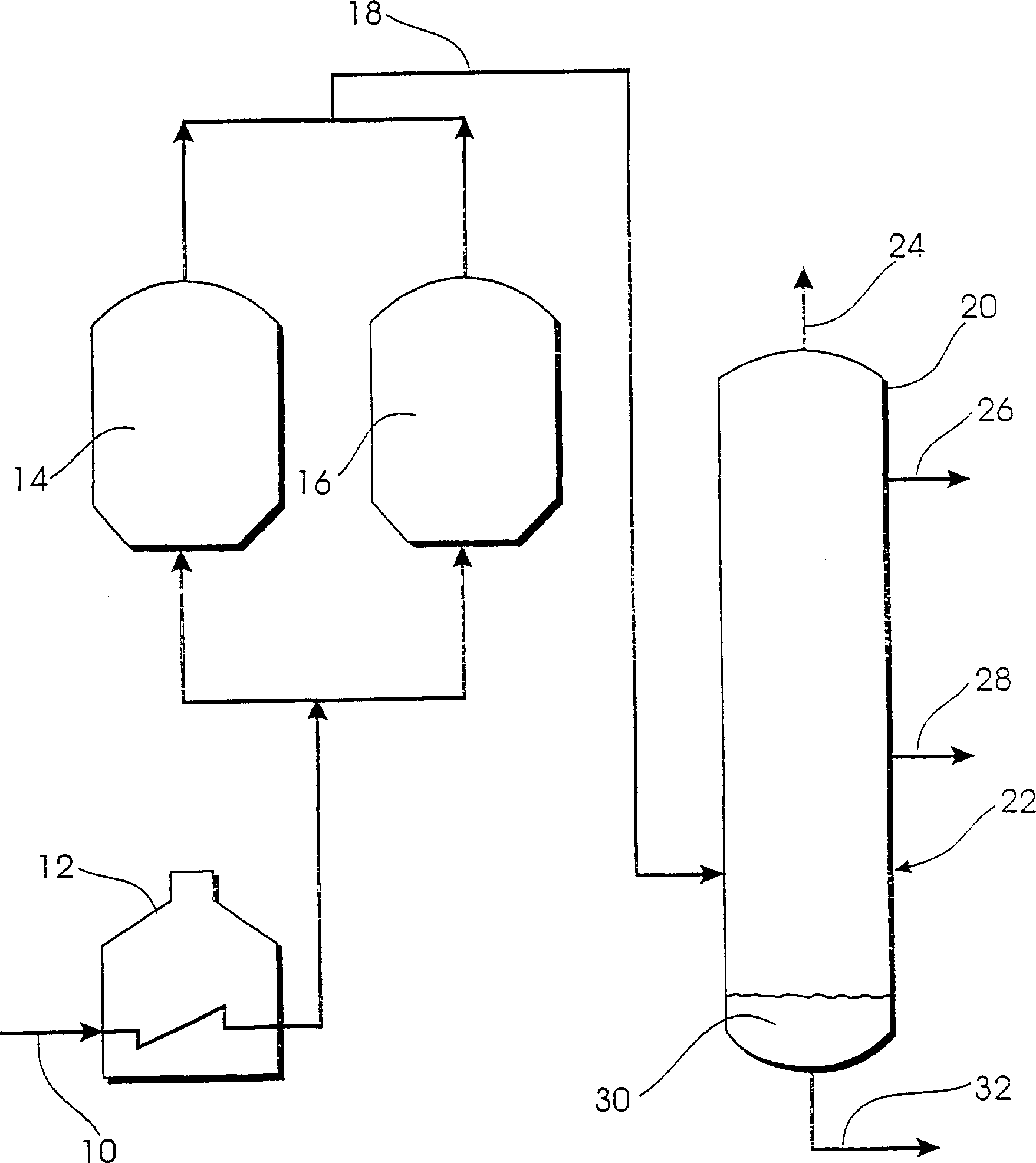
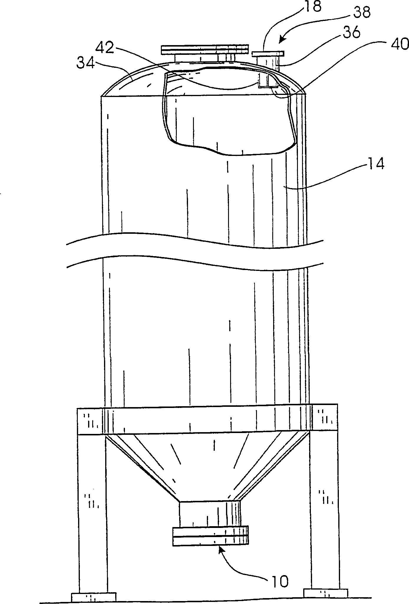
[0018] figure 1 A simplified conventional coker is shown in which coking feedstock is passed from line 10 to furnace 12 where it is heated. figure 1 The layout of the present invention uses a coking tower, but it should be understood that the present invention can be used in single tower or multiple tower situations. Coking drums 14 and 16 are alternately filled and emptied. When a coking drum is full of solid coke, the coke can be withdrawn at least near the bottom (and usually the top).

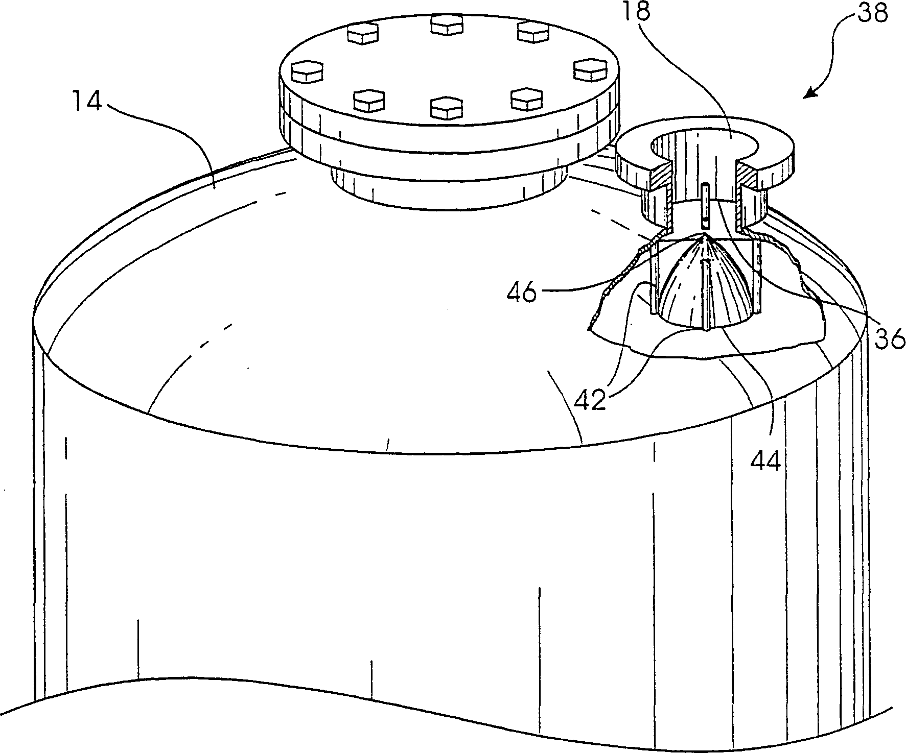
[0019] Overhead vapor from the packed coker is returned to coker fractionator 20 via line 18 . Recovered liquid, such as coker gas oil or coker feedstock, is sent to fractionator 20 via line 22 . An overhead wet gas stream is withdrawn from fractionator 20 via line 24 and an intermediate liquid fraction is withdrawn via lines 26 and 28 . Unwanted solids and heavy hydrocarbon liquids 30 are withdrawn from the bottom of fractionator 20 via line 32 and directed to the furnace. Other modif...


PUM


Abstract

An improved delayed coker having at least one coking drum (14), wherein said coking drum includes a substantially closed interior, a top (34) having an aperture (36), a tower removably connected to said aperture top steam outlet nozzles (38), and deflector plates (40) for deflecting solids and heavy hydrocarbon liquids exiting from said interior of said coking drum through said holes.

Description

technical field [0001] The present invention relates to a delayed coking process. In particular, the present invention relates to a deflector plate placed in the top of the coking tower below the overhead vapor outlet nozzle to reduce the amount of solids and heavy hydrocarbon liquids escaping through the outlet nozzle of the coking tower and returning to the fractionator. Background technique [0002] During the operation of delayed coking towers used to coke various heavy hydrocarbon materials in oil refining, heavy hydrocarbons are pyrolyzed to produce gaseous, liquid and solid coke. Typically, the fractionator is fed, then the fractionator bottoms are removed and heated in a furnace, causing further pyrolysis. The resulting solid coke is gradually deposited on the inner wall of the coking tower. In a common delayed coker, a coker drum is filled and emptied alternately, with coking feedstock being pumped into one drum while the other drum is emptied of coke in preparati...

Claims


Application Information

Patent Timeline
Patent Type & Authority Applications(China)
IPC IPC(8): C10B57/04B01D45/04B01D45/08C10B1/04C10B27/06C10B55/00
CPCB01D45/04B01D45/08C10B1/04C10B27/06C10B55/00
Inventor 吉姆·R·罗思哈里·R·詹森加里·C·休斯布赖恩·J·德克森
Owner CONOCO INC
Why Eureka
Try Eureka