Mist catcher for gas-liquid separation
A gas-liquid separation and mist trap technology, applied in separation methods, dispersed particle separation, chemical instruments and methods, etc., can solve the problem of secondary carryover of droplets, reduce secondary carryover, improve collection effect, and reduce fragmentation the effect of the situation
- Summary
- Abstract
- Description
- Claims
- Application Information
AI Technical Summary
Problems solved by technology
Method used
Image
Examples
Embodiment 1
[0027] Embodiment one: refer to Figure 8 , a mist catcher for gas-liquid separation, comprising an outer cover 10, the inside of the outer cover 10 is provided with a folded plate 11, in this scheme, the folded plate 11 is installed in a horizontal direction, and the outer wall of the outer cover 10 is provided with an air inlet 13, and the air intake The number of ports 13 is two and located at both ends of the outer cover 10 respectively. The gas-liquid mixture enters from the two air inlets 13 respectively, which effectively improves the separation efficiency. The flap 11 divides the inner cavity of the outer cover 10 into multiple air cavities A one-way communication pipe 12 is connected between two adjacent air chambers, and the one-way communication pipe 12 can only transport gas from bottom to top. At the same time, the two oppositely flowing gas-liquid mixtures also collide, which not only reduces the flow velocity of the gas-liquid mixture, but also the divergent gas...
Embodiment 2
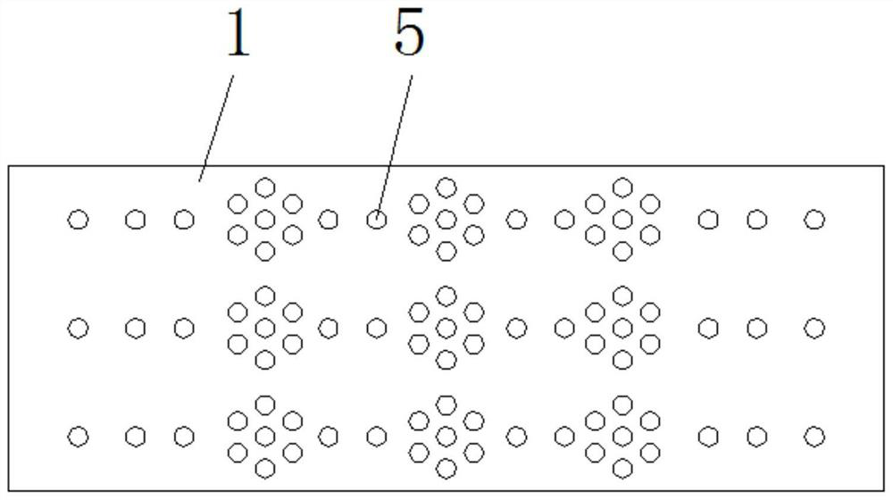
[0031] Embodiment 2: The difference from Embodiment 1 is that the positive plate 1 with holes originally opened at the uppermost end of the fixing plate 4 is formed by combining the positive plate 1 and the baffle plate 9; refer to Figure 4-6 , both sides of the baffle plate 9 are provided with a positive plate 1, the baffle plate 9 and the positive plate 1 are seamlessly connected, the surface of the positive plate 1 bends toward the direction of the baffle plate 9, and the positive plate 1 is arranged on both sides of the baffle plate 9. A hole is opened on the baffle 9, and the bottom surface of the baffle 9 is connected to the capillary 5. The positive plate 1 is used to form an electric field with the negative plate 2 on the other folded plate 11, and attract negatively charged droplets to move, and the droplets move to the positive plate 1 When the surface is on the surface, it slides inwardly and gathers on the baffle plate 9, and then collects the liquid through the ca...
Embodiment 3
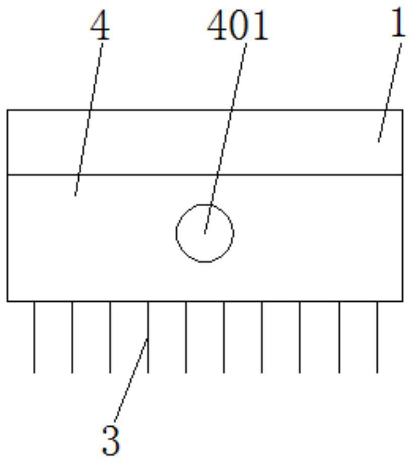
[0032] Embodiment 3: Different from Embodiment 1, the positive plate 1 is located inside the solid plate 4, and the positive plate 1 that is directly in contact with the gas-liquid mixture is replaced by a baffle 9; the zero potential conductor 6 is located at the port and does not penetrate The inside of the whole liquid chamber 8 avoids affecting the electric field lines obtained by the negative plate 2; refer to Figure 7 , the positive plate 1 is located inside the solid plate 4, the positive plate 1 and the negative plate 2 are respectively located on both sides of the insulator 7, the baffle plate 9 and the negative plate 2 are respectively located at the upper and lower ends of the solid plate 4, and the liquid chamber 8 is formed by the positive plate 1. In the space enclosed by the solid plate 4 and the baffle 9, the zero-potential conductor 6 is located at the liquid hole 401 of the solid plate 4 for liquid outlet; in this scheme, the baffle 9 needs to be made of a ma...
PUM
 Abstract
Description
Claims
Application Information
 - R&D
- Intellectual Property
- Life Sciences
- Materials
- Tech Scout
- Unparalleled Data Quality
- Higher Quality Content
- 60% Fewer Hallucinations
Browse by: Latest US Patents, China's latest patents, Technical Efficacy Thesaurus, Application Domain, Technology Topic, Popular Technical Reports.
© 2025 PatSnap. All rights reserved.Legal|Privacy policy|Modern Slavery Act Transparency Statement|Sitemap|About US| Contact US: help@patsnap.com


