Film-releasing condensation vacuum system

A vacuum system and vacuum pump technology, applied in steam/steam condensers, lighting and heating equipment, etc., can solve the problems of vacuum pump pumping capacity reduction, pipeline vibration, and increased floor space, so as to improve pumping efficiency and reduce exhaust With water, the effect of intense heat transfer

Pending Publication Date: 2017-07-18
CENT SOUTHERN CHINA ELECTRIC POWER DESIGN INST CHINA POWER ENG CONSULTING GROUP CORP
View PDF7 Cites 0 Cited by
  • Summary
  • Abstract
  • Description
  • Claims
  • Application Information

AI Technical Summary

Problems solved by technology

This type of system requires a nozzle on the upper part of the condensation tank and an atomization device in front of the nozzle, which makes the entire condensation vacuum system very complicated, and after water atomization, there are many small droplets that will be entrained by the rising airflow to condense The device forms a gas-liquid two-phase flow. The gas-liquid two-phase flow can easily cause pipeline vibration during high-speed motion, which will cause the vacuum pump to reduce the suction volume, and easily cause the vacuum system to exhaust steam and carry water.
If a vapor-liquid separation device is used on the top of the condensing tank of the condensing vacuum system, the complexity and investment of the system will be further increased, and the floor space will be increased.
Due to the fast flow of steam in the condensing tank, the insufficient residence time also leads to a decrease in the condensation efficiency of the steam, and a large number of liquid droplets are entrained to leave the condensing tank, resulting in loss of working fluid

Method used


Image

  • Film-releasing condensation vacuum system
  • Film-releasing condensation vacuum system
  • Film-releasing condensation vacuum system

Examples


Embodiment Construction

[0024] The implementation of the present invention will be described in detail below in conjunction with the accompanying drawings, but they do not constitute a limitation to the present invention, they are only examples, and at the same time, the advantages of the present invention will become clearer and easier to understand.

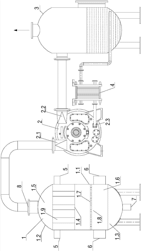
[0025] A kind of film forming condensation vacuum system of the present invention, it comprises film forming condensing device 1, vacuum pump 2, vapor-water separator 3 and heat exchanger 4; The suction port 8 on the top of described film forming condensing device 1 is connected with described film forming condensing device 1 through pipeline The suction port 2.1 of the vacuum pump 2 is connected, and the discharge port 2.2 of the vacuum pump 2 is connected with the steam-water separator inlet 3.1 on the top of the steam-water separator 3 through a pipeline, and the steam-water separator 3.1 is connected with the vacuum pump 2 through the heat exchanger...


PUM


Abstract

The invention discloses a film-releasing condensation vacuum system which comprises a film-releasing condensing unit (1), a vacuum pump (2), a steam-water separation device (3) and a heat exchanger (4), wherein an air exhaust port (8) in the top of the film-releasing condensing unit (1) is connected with a suction inlet (2.1) of the vacuum pump (2) through a pipeline; an exhaust port (2.2) of the vacuum pump (2) is connected with a steam-water separation device inlet (3.1) in the upper part of the steam-water separation device (3) through a pipeline; the steam-water separation device (3) is connected with a water return inlet (2.3) of the vacuum pump (2) through the heat exchanger (4); and a condensation water draining port (7) formed in the bottom end of the film-releasing condensing unit (1) is connected with a condenser hot well of a power plant. The film-releasing condensation vacuum system overcomes the defects in the prior art that a vacuum pump is likely to cavitation and increases working medium loss and has the advantages of being simple and efficient, convenient to arrange, free of additional equipment and integrally arranged, reducing the occupied space, and reducing the cost.

Description

technical field [0001] The invention relates to the technical field of condensing devices, and more specifically relates to a film-forming condensing vacuum system. Background technique [0002] Due to the limitation of the water source and the floor area where the power station is located, most power stations in China currently operate in indirect water cooling or air cooling. For indirect water-cooled or air-cooled power plants, the thermal efficiency is significantly affected by the back pressure of the turbine operation. When the back pressure of the turbine, that is, the exhaust pressure is higher than the blocking back pressure, reducing the back pressure of the turbine can significantly improve the thermal efficiency of the unit. The operating back pressure of the steam turbine is mainly limited by the vacuum degree of the condensing system, which depends on whether the condenser system can efficiently condense the exhaust steam of the steam turbine into water. [00...

Claims


Application Information

Patent Timeline
IPC IPC(8): F28B9/10
CPCF28B9/10
Inventor 桂本王国贵闵山山徐传海李至周天情匡云黄军军刘杰刘伟峰
Owner CENT SOUTHERN CHINA ELECTRIC POWER DESIGN INST CHINA POWER ENG CONSULTING GROUP CORP
Why Eureka
Try Eureka