
Large-span prefabricated bridge structure

A bridge structure, large-span technology, applied in the direction of bridges, bridge parts, bridge materials, etc., can solve the problems of corrosion of steel bars, large rotation of beam ends, cracks, etc., to improve tensile strength, comfort, and durability. Effect

Active Publication Date: 2015-06-17
SHENZHEN MUNICIPAL DESIGN & RES INST
View PDF7 Cites 0 Cited by
  • Summary
  • Abstract
  • Description
  • Claims
  • Application Information

AI Technical Summary

Problems solved by technology

[0003] At present, there are three types of continuous bridge decks that are most commonly used: 1. Consolidated continuous slabs made of reinforced concrete slabs with rectangular cross-sections. Penetration is easy to cause corrosion of steel bars
2. The hinged continuous slab made of reinforced concrete slab, although the mechanical performance of this form is improved, because the slab end can release its tensile stress, but the structure is complicated and the construction is inconvenient; 3. The connection is made of thick steel bars Rods, that is, the ends of the cast-in-place layer on the top surface of the main beam with two adjacent holes are connected with thick steel bars with high strength, relying on the steel bars to transmit horizontal force, and the two ends of the steel bars are anchored in the cast-in-place layer at the top of the beam
[0004] Experience shows that with the increase of the span of the prefabricated beam, the reserved space between the gaps will be larger, so the deflection of the beam body will be larger after loading, and the rotation of the beam end will be larger. The above continuous bridge deck device is prone to cracking, affecting Durability and driving comfort of the bridge deck
This type of bridge deck continuous device is currently limited to a maximum span of 35m

Method used


Image

  • Large-span prefabricated bridge structure
  • Large-span prefabricated bridge structure
  • Large-span prefabricated bridge structure

Examples


Embodiment Construction

[0025] The following will clearly and completely describe the technical solutions in the embodiments of the present invention with reference to the accompanying drawings in the embodiments of the present invention. Obviously, the described embodiments are only some, not all, embodiments of the present invention. Based on the embodiments of the present invention, all other embodiments obtained by persons of ordinary skill in the art without creative efforts fall within the protection scope of the present invention.

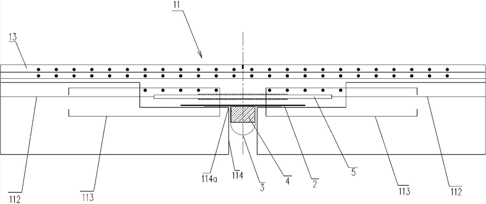
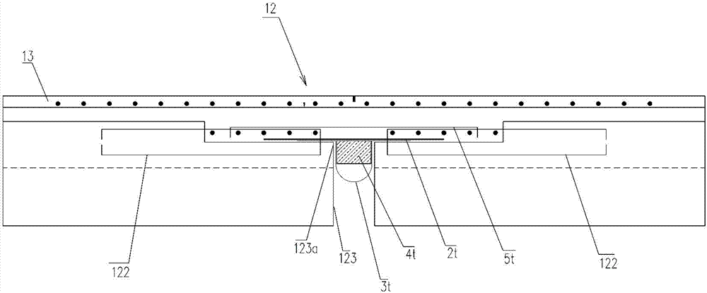
[0026] see in conjunction Figure 1-Figure 4 , is Embodiment 1 of the long-span prefabricated bridge structure of the present invention.

[0027] The bridge deck continuous structure of the long-span prefabricated bridge in this embodiment includes a beam body 1, wherein, figure 1 Shown is a schematic diagram of the 1 / 2 elevation structure of the beam body. The beam body 1 is provided with connected beam rib area 11 and beam wing plate area 12 in sequence along i...


PUM


Abstract

The invention discloses a large-span prefabricated bridge structure. The large-span prefabricated bridge structure comprises a beam body, wherein the beam body is sequentially provided with a beam rib area and a beam wing plate area which are connected in the longitudinal direction of the beam body. Bridge floor cast-in-place layers are arranged on the tops of the beam rib area and the beam wing plate area. The beam rib area is provided with a plurality of first cross-joint force-bearing assemblies which are arranged at intervals and a plurality of first buried assemblies arranged at intervals. The first cross-joint force-bearing assemblies and the first embedded assemblies are welded and connected. The beam wing plate area is provided with a plurality of second cross-joint force-bearing assemblies which are arranged at intervals and a plurality of second buried assemblies arranged at intervals. The second cross-joint force-bearing assemblies and the second buried assemblies are arranged in the transverse direction of a large-span prefabricated bridge. The second cross-joint force-bearing assemblies and the second buried assemblies are welded and connected. By means of the large-span prefabricated bridge structure, the tensile strength of breaking joint positions is improved, and therefore cracks at end joints are reduced, the influences of water seepage caused after a bridge floor cracks on the beam body are reduced, and the durability of the bridge is improved.

Description

technical field [0001] The invention relates to the engineering field, in particular to a large-span prefabricated bridge structure applied to a span of more than 35m. Background technique [0002] Prefabricated hollow slabs and prefabricated T-beams are commonly used structural forms, which can reduce the impact of construction on road traffic, and these structures require continuous bridge deck design at the fracture joints. [0003] At present, there are three types of continuous bridge decks that are most commonly used: 1. Consolidated continuous slabs made of rectangular cross-section reinforced concrete slabs. Penetration can easily cause steel corrosion. 2. The hinged continuous slab made of reinforced concrete slab, although the mechanical performance of this form is improved, because the slab end can release its tensile stress, but the structure is complicated and the construction is inconvenient; 3. The connection is made of thick steel bars Rods, that is, the en...

Claims


Application Information

Patent Timeline
IPC IPC(8): E01D2/00E01D19/00E01D19/12E01D19/06
CPCE01D2/00E01D19/083E01D19/125E01D2101/266
Inventor 彭栋木刘妍祈巍陈宜言梁余流许有胜金勇查理·菲尔费德
Owner SHENZHEN MUNICIPAL DESIGN & RES INST
Learn More