Variable valve timing mechanism with middle locking function
A technology of valve timing and intermediate lock, which is applied in the direction of mechanical equipment, engine components, machines/engines, etc. It can solve the problems of uncoordinated engine intake and exhaust work, change of valve timing, and low combustion efficiency, so as to facilitate assembly , increase the area, improve the effect of combustion efficiency
- Summary
- Abstract
- Description
- Claims
- Application Information
AI Technical Summary
Problems solved by technology
Method used
Image
Examples
Embodiment 1
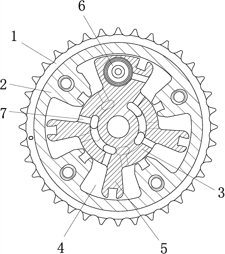
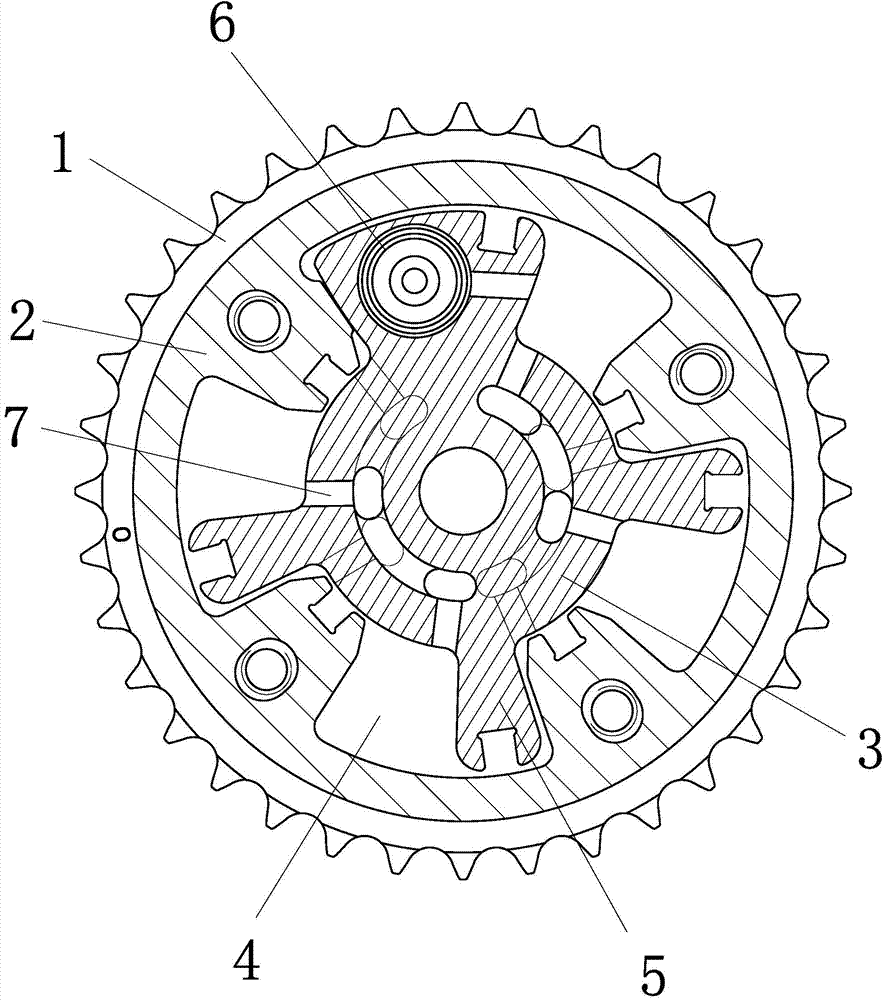
[0019] Embodiment 1: as figure 1 , 2 As shown, a variable valve timing mechanism with an intermediate locking function includes a sprocket 1, a stator 2 and a rotor 3 are arranged coaxially inside the sprocket, and the rotor 2 is located in the stator 3. The inner wall of the stator is provided with four adjustable accommodation cavities 4, which are fan-shaped, and the outer wall of the rotor is integrally connected with four adjustable rotating arms 5, and the four adjustable rotating arms are respectively located in the four adjustable accommodation cavities. Radial oil passages 7 are arranged on the rotor. A locking mechanism 6 is arranged on the rotor, and the locking mechanism is a threaded fixed disk, which is threadedly connected with the rotor and conflicts with the bottom surface of the adjustable accommodating cavity. The bottom surface of the adjustable accommodating cavity is a guiding inclined surface, which is inclined towards the axis of the stator, and the b...
Embodiment 2
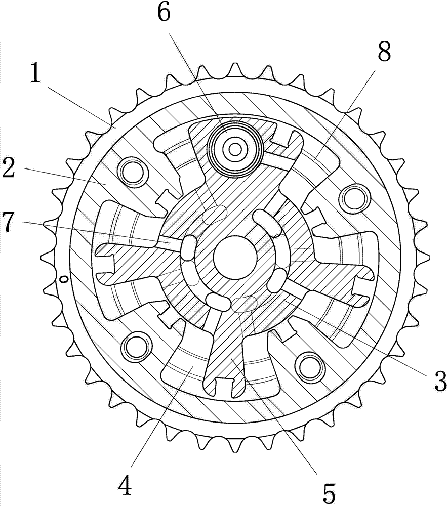
[0021] Embodiment 2: The structure of this embodiment is basically the same as that of Embodiment 1, the difference is that, as image 3 , 4 As shown, there are two slide grooves 8 on the bottom surface of the adjustable accommodating chamber, the slide grooves are arc-shaped grooves with the axial center of the stator as the center of the circle, and the bottom surface of the adjustable rotating arm is provided with a raised slide rail 9. slots to match. The cross section of the chute is "V" shaped, and the cross section of the slide rail is the same as that of the chute and fitted together.
[0022]The bottom surface of the adjustable accommodating cavity is provided with at least one chute, the chute is an arc-shaped groove centered on the axis of the stator, the bottom surface of the adjustable arm is provided with a raised slide rail, the slide rail cooperates with the chute, and the The contact surface between the adjustable rotating arm and the bottom surface of the a...
Embodiment 3
[0023] Embodiment 3: The structure of this embodiment is basically the same as that of Embodiment 1 or 2, the difference is that, as Figure 5 As shown, the bottom surface of the adjustable accommodating chamber is a guiding slope, and the guiding slope is inclined toward the axis of the stator. The thickness of the guiding slope increases from the axis toward the outer edge. . The bottom surface of the adjustable accommodating chamber is provided with two slide grooves. The slide grooves are arc-shaped grooves with the axial center of the stator as the center of a circle. The bottom surface of the adjustable rotating arm is provided with a raised slide rail, and the slide rails cooperate with the slide grooves. The cross section of the chute is "V" shaped, and the cross section of the slide rail is the same as that of the chute and fitted together.
PUM
 Abstract
Description
Claims
Application Information
 - R&D
- Intellectual Property
- Life Sciences
- Materials
- Tech Scout
- Unparalleled Data Quality
- Higher Quality Content
- 60% Fewer Hallucinations
Browse by: Latest US Patents, China's latest patents, Technical Efficacy Thesaurus, Application Domain, Technology Topic, Popular Technical Reports.
© 2025 PatSnap. All rights reserved.Legal|Privacy policy|Modern Slavery Act Transparency Statement|Sitemap|About US| Contact US: help@patsnap.com


