Water heater heat exchanger and manufacturing method thereof

A manufacturing method and heat exchanger technology, applied in the direction of fluid heaters, lighting and heating equipment, etc., can solve the problems of low efficiency and low strength of aluminum alloy heat exchangers, and achieve cost reduction, pollution-free water quality, and convenient installation Effect

Active Publication Date: 2015-06-17
WUHU MIDEA SMART KITCHEN APPLIANCE MFG CO LTD
View PDF7 Cites 1 Cited by
  • Summary
  • Abstract
  • Description
  • Claims
  • Application Information

AI Technical Summary

Problems solved by technology

However, the production of existing heat exchangers needs to wear several fins on the heat conduction tubes, and set coiled tubes around the combustion chamber, which not only has low efficiency, but also produces aluminum alloy heat exchangers with low strength.

Method used


Image

  • Water heater heat exchanger and manufacturing method thereof
  • Water heater heat exchanger and manufacturing method thereof
  • Water heater heat exchanger and manufacturing method thereof

Examples


Embodiment Construction

[0045] It should be understood that the specific embodiments described here are only used to explain the present invention, not to limit the present invention.

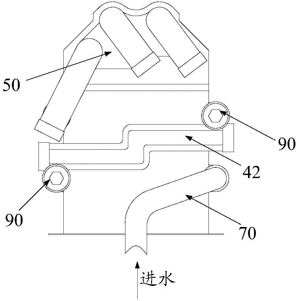
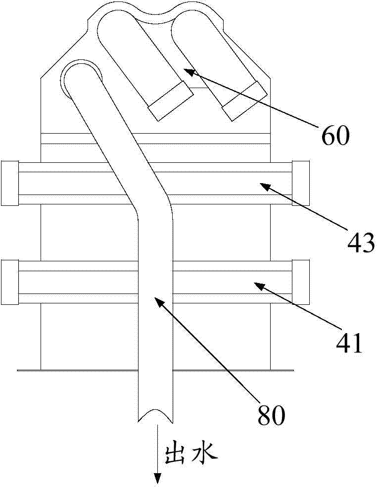
[0046] The invention provides a heat exchanger. Such as Figure 1 to Figure 3 as shown, figure 1 It is a schematic diagram of the front view structure of the heat exchanger of the present invention; figure 2 for figure 1 The structural schematic diagram of the right side view of the heat exchanger shown; image 3 for figure 1 Shown is a structural schematic diagram of the left side view of the heat exchanger of the present invention. The heat exchanger includes a heat exchange main body, a left end cover 60 , a right end cover 50 , a water inlet pipe 70 , a water outlet pipe 80 and a plug 90 .

[0047] Specifically, such as Figure 4 to Figure 6 as shown, Figure 4 for figure 1 The schematic diagram of the cross-sectional structure of the heat exchanger along the line A-A; Figure 5 for figure 1 The schema...


PUM


Abstract

The invention discloses a water heater heat exchanger which comprises a water inlet tube, a water outlet tube, a first group of communicating tubes, a second group of communicating tubes and a heat exchange main body which comprises a combustor, heat conduction tubes and a heat exchange fin which are formed by integral die-casting forming through aluminum alloy, three or more heat conduction tubes are arranged, and each heat conduction tube protrudes out of the first end and the second end of the heat exchange main body; the first group of communicating tubes and the water inlet tube are located at the first end of the heat exchange main body, the water inlet tube is used for being communicated with one heat conduction tube which protrudes out of the first end of the heat exchange main body, and the first group of communicating tubes is used for being communicated with the rest heat conduction tubes which protrude out of the first end of the heat exchange main body; the second group of communicating tubes and the water outlet tube are located at the second end of the heat exchange main body, the water outlet tube is used for being communicated with one heat conduction tube which protrudes out of the first end of the heat exchange main body, and the second group of communicating tubes is used for being communicated with the rest heat conduction tubes which protrude out of the first end of the heat exchange main body. The invention further discloses a manufacturing method of the water heater heat exchanger. The water heater heat exchanger and the manufacturing method thereof have the advantages that the cost is reduced, and the overall strength and the heat conduction efficiency of the heat exchanger are improved.

Description

technical field [0001] The invention relates to the technical field of water heaters, in particular to a water heater heat exchanger and a manufacturing method thereof. Background technique [0002] The heat exchange structure of the existing gas water heater heat exchanger is made of copper heat pipes interspersed in the fins, but the production cost of copper is relatively high, so people start to use aluminum alloy with low cost for production. However, the production of existing heat exchangers needs to wear some fins on the heat conduction tubes, and arrange coiled tubes around the combustion chamber, which not only has low efficiency, but also produces aluminum alloy heat exchangers with low strength. Contents of the invention [0003] The main purpose of the present invention is to provide a water heater heat exchanger and a manufacturing method thereof, aiming at saving costs and improving the strength of the water heater heat exchanger. [0004] In order to achie...

Claims


Application Information

Patent Timeline
Patent Type & Authority Applications(China)
IPC IPC(8): F24H9/00B23P15/26
Inventor 陈文风唐晓峨但清海
Owner WUHU MIDEA SMART KITCHEN APPLIANCE MFG CO LTD
Why Eureka
Try Eureka