
Analysis system and method of medium motion state in ball mill

A medium motion and analysis system technology, applied in the direction of navigation and grain processing through velocity/acceleration measurement, can solve the problems of camera lens pollution, dim light, large errors, etc., to reduce energy consumption and production costs.

Active Publication Date: 2015-06-17
CHINA NAT OFFSHORE OIL CORP +3
View PDF3 Cites 17 Cited by
  • Summary
  • Abstract
  • Description
  • Claims
  • Application Information

AI Technical Summary

Problems solved by technology

[0003] In the prior art, the camera video monitoring method is used to observe the movement state of the media inside the ball mill, but this method can only be used to monitor the movement on both sides of the end cover of the ball mill; The body and the camera lens are easily polluted by water vapor, dust, mud, etc., and it is difficult to observe; the detection ball that can realize the motion measurement of the ball mill medium in the prior art discloses a monitoring system based on a gyroscope, an accelerometer, and a magnetoresistive sensor. However, in practical applications, since the ball mill cylinder is generally made of metal materials, the magnetoresistive sensor cannot work in a metal container.
In addition, gyroscopes and accelerometers, especially the ADXL345 and L3G4200D mentioned in this patent, have relatively large errors, and the error of velocity and position information obtained by the integral method is even greater. Therefore, the current method for analyzing the motion state of the medium inside the ball mill has large errors and cannot be effective. reflect the grinding efficiency of the ball mill

Method used


Image

  • Analysis system and method of medium motion state in ball mill
  • Analysis system and method of medium motion state in ball mill
  • Analysis system and method of medium motion state in ball mill

Examples


Embodiment Construction

[0036] The present invention will be described in detail below in conjunction with the accompanying drawings and embodiments.

[0037] The analysis system of the motion state of the medium in the ball mill of the present invention includes a plurality of ball mill sensors 1 and a host computer; each ball sensor 1 sends the collected data of the motion state of the medium in the ball mill to the host computer, and the host computer checks the grinding balls. The motion state data is analyzed and processed; wherein, the medium motion state data includes time stamp, 3-axis acceleration and 3-axis angular velocity.

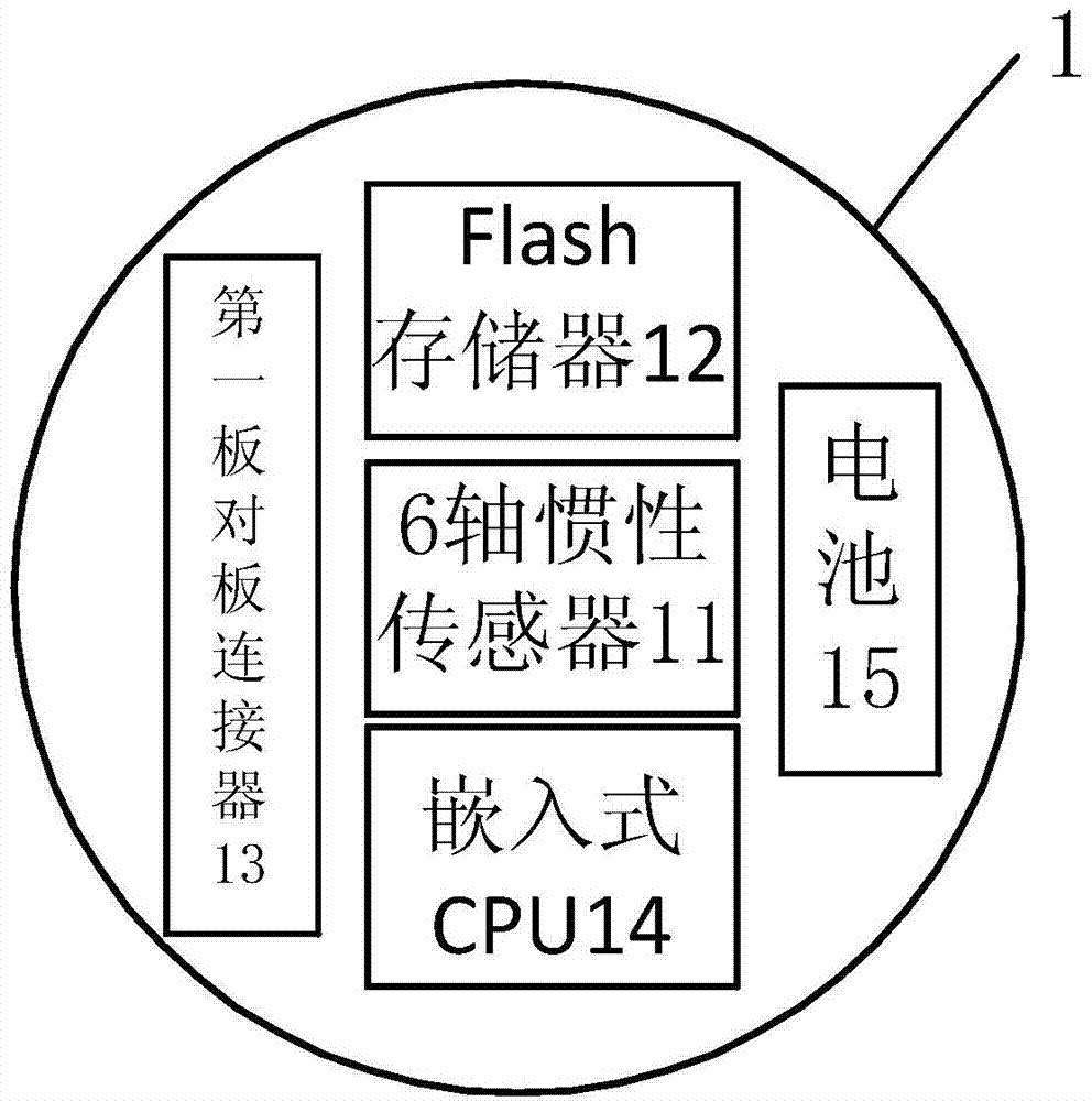
[0038] Such as figure 1 As shown, the ball sensor 1 of the present invention includes a 6-axis inertial sensor 11, a Flash memory 12, a first board-to-board connector 13, an embedded CPU 14 and a battery 15, wherein the 6-axis inertial sensor 11, The Flash memory 12, the first board-to-board connector 13 and the embedded CPU 14 are all fixedly arranged on a circuit b...


PUM


Abstract

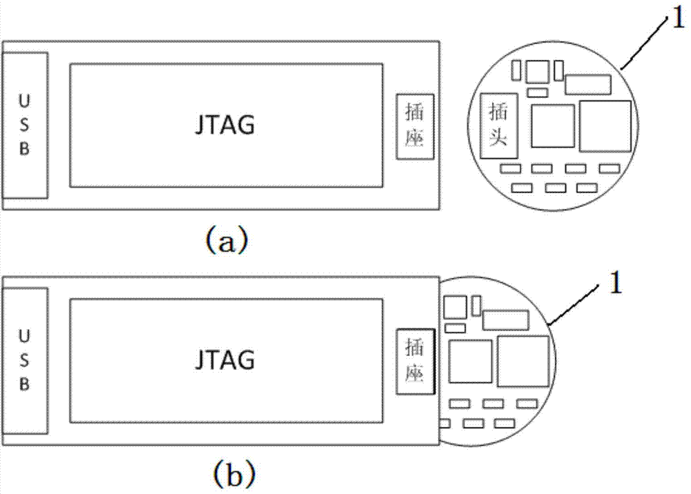
The invention relates to an analysis system and a method of a medium motion state in a ball mill. The analysis system comprises a plurality of mill ball sensors and an upper computer, wherein each mill ball sensor transmits acquired medium motion state data in the ball mill to the upper computer; the upper computer analyzes and processes the mill ball motion state data; the mill ball sensors comprise six-axis inertia sensors, Flash memories, first plate-plate connector, embedded CPUs (central processing units) and batteries; the six-axis inertia sensors transmit the acquired medium motion state data in the ball mill to the embedded CPUs; the embedded CPUs transmit the received medium motion state data in the ball mill to the Flash memories; after completion of data acquisition, the embedded CPUs read contents in the Flash memories and transmit the acquired data to the upper computer via the first plate-plate connectors and extension interface circuit boards; the batteries are used for supplying power to the six-axis inertia sensors, the Flash memories and the embedded CPUs; and the upper computer comprises a ball mill information management module, a mill ball sensor management module and an experimental data management module.

Description

technical field [0001] The invention relates to the field of ball mills, in particular to a system and method for analyzing the motion state of a medium in a ball mill. Background technique [0002] Ball mill is a kind of traditional grinding equipment, which realizes the crushing of materials by the impact and grinding of media (grinding balls) on materials. When the cylinder rotates around the central axis, the grinding balls and materials rise to a certain height with the cylinder wall under the action of centrifugal force and friction force, and then fall away and fall away. With the continuous rotation of the cylinder, the materials between the media are constantly impacted and ground by the media, and finally crushed. Compared with other grinding equipment, the ball mill has the advantages of wide material adaptability, simple operation and maintenance, and high reliability, but it also has the disadvantages of low work efficiency and high power consumption. Therefor...

Claims


Application Information

Patent Timeline
Patent Type & Authority Applications(China)
IPC IPC(8): G01C21/16B02C25/00
CPCB02C17/10B02C25/00G01C21/16B02C17/1805B02C17/20
Inventor 姜振胜姚光前李松涛王晗杨爵杨广柱卢忠瑜原航辉傅克文安平刘亭
Owner CHINA NAT OFFSHORE OIL CORP
Learn More