Liquid crystal display screen detecting device
A detection device and liquid crystal screen technology, applied in nonlinear optics, instruments, optics, etc., can solve the problems of inability to operate multiple detection devices at the same time, inability to draw an electromagnetic pen across the electromagnetic screen, and high labor intensity for inspection personnel. Good driving effect, easy installation and maintenance, low weight
- Summary
- Abstract
- Description
- Claims
- Application Information
AI Technical Summary
Problems solved by technology
Method used
Image
Examples
Embodiment 1
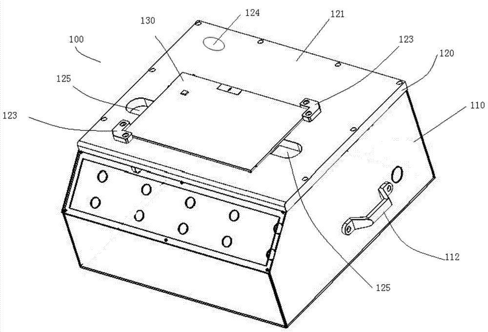
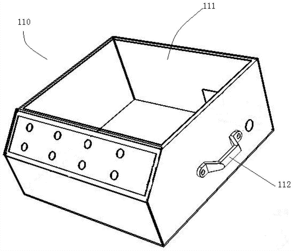
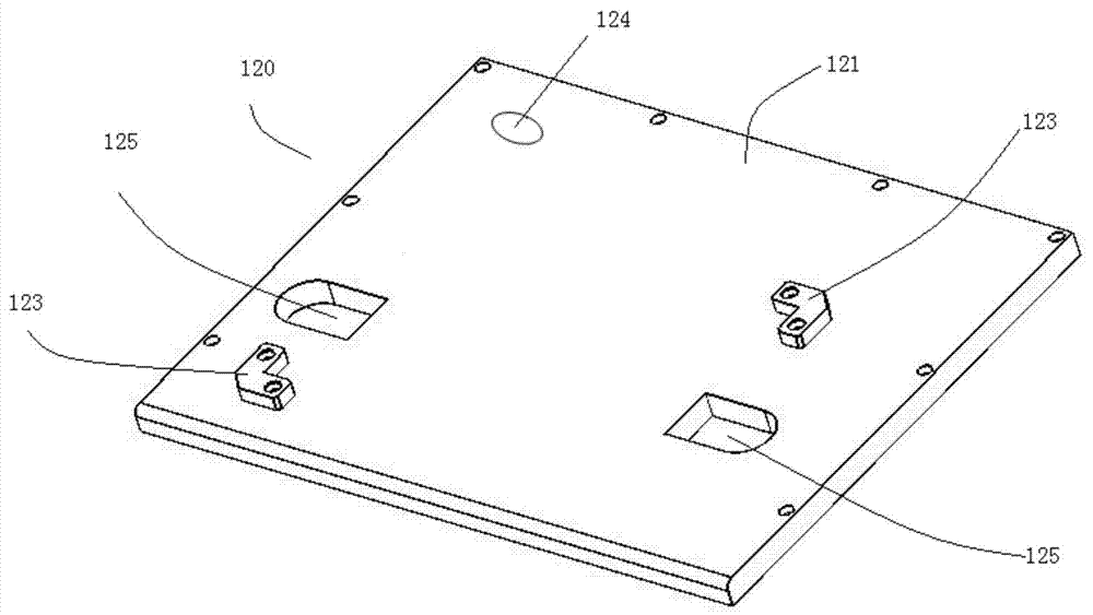
[0050] Such as figure 1 As shown, the liquid crystal screen testing device 100 includes a box body 110 and a support plate 120 for fixing the liquid crystal screen 130 . The upper surface 121 of the support plate 120 is used for fixing the liquid crystal screen 130 . There is a movable signal transmitting device below. The signal transmitting device is used to transmit a signal to the liquid crystal screen 130, and according to the response of the liquid crystal screen 130 to the signal, it can be judged whether the performance of the liquid crystal screen 130 is normal. In the example shown in the figure, the signal transmitting device is an electromagnetic pen 140 . The electromagnetic pen 140 emits electromagnetic wave signals towards the liquid crystal screen 130 . According to the response of the liquid crystal screen 130 to the electromagnetic wave signal, the quality of the liquid crystal screen 130 can be judged.
[0051] Such as figure 1 , figure 2 As shown, th...
Embodiment 2
[0063] Such as Figure 6 As shown, the difference between this embodiment and Embodiment 1 is that an air cylinder 190 is used as the driving device instead of the asynchronous motor 170 in Embodiment 1. The air cylinder 190 is mounted on the lower surface 122 of the support plate 120 . Cylinder 190 is a two-way motion cylinder. The air cylinder 190 includes a cylinder body 191 and a piston rod 192 . The piston rod 192 is telescopically disposed on the cylinder body 191 . The end of the piston rod 192 is connected with the slider 152 . By adopting the cylinder 190, the present embodiment does not need to use the transmission belt 173 and the driving wheel 172, the supporting wheel 174 and the tensioning wheel 175 matched with the transmission belt 173. The air cylinder 190 communicates with an air supply device (not shown in the figure) through an air supply pipeline, and the air supply device provides an air source. A solenoid valve is set on the gas supply pipeline to c...
Embodiment 3
[0066] Such as Figure 7 As shown, the difference between this embodiment and Embodiment 1 is that a linear motor is used to replace the asynchronous motor 170 , guide rail 151 and slider 152 in Embodiment 1. The linear motor includes coil windings 196 and permanent magnet bars 197 . Permanent magnet bars 197 are mounted on the lower surface 122 of the support plate 120 . The coil winding 196 is set on the permanent magnet bar 197 and can move along the permanent magnet bar 197 . Base 160 is mounted on coil winding 196 . Adopt linear motor, present embodiment needn't use asynchronous motor 170, transmission belt 173 and the driving wheel 172 that cooperates with transmission belt 173, support wheel 174 and tension wheel 175, and also do not need guide rail 151 and slide block 152.
[0067] The rest of the structure of this embodiment is the same as that of Embodiment 1.
[0068] The coil winding 196 can be reciprocated on the permanent magnet bar 197 by using the currents ...
PUM
 Abstract
Description
Claims
Application Information
 - R&D Engineer
- R&D Manager
- IP Professional
- Industry Leading Data Capabilities
- Powerful AI technology
- Patent DNA Extraction
Browse by: Latest US Patents, China's latest patents, Technical Efficacy Thesaurus, Application Domain, Technology Topic, Popular Technical Reports.
© 2024 PatSnap. All rights reserved.Legal|Privacy policy|Modern Slavery Act Transparency Statement|Sitemap|About US| Contact US: help@patsnap.com


