
Waveguide 90-degree turning structure with polarization turning function

A horizontally polarized wave and waveguide technology, applied to waveguide devices, electrical components, circuits, etc., can solve the problems of large volume, no torsional polarization, system performance and reliability degradation, etc.

Inactive Publication Date: 2015-06-17
PIVOTONE COMM TECH
View PDF6 Cites 19 Cited by
  • Summary
  • Abstract
  • Description
  • Claims
  • Application Information

AI Technical Summary

Problems solved by technology

No matter which method is used, two components are required, which is not only large in size, high in cost, and inflexible in assembly; too many components will also lead to a decrease in system performance and reliability
In addition, if the twisted waveguide method is used, it cannot be processed by conventional machining, and must have a special processing technology, which further increases the cost of the product.
[0003] In the prior art (patent number: ZL 2012 20174272.X), the 90-degree turning mechanism of the microwave waveguide can only turn the direction of microwave propagation by 90 degrees, without the function of torsional polarization. To realize the function of torsional polarization, two Only one microwave waveguide 90-degree turning mechanism can be realized, which will increase the cost and volume, and will also deteriorate the electrical performance indicators of the system.
[0004] Another patent application 201410454504.0 is a microwave waveguide pipe 90-degree turning mechanism with polarization twisting function. The two waveguide ports between the vertical polarizations of the polarization twister cannot be symmetrical with the center line, so it is not applicable in many occasions.

Method used


Image

  • Waveguide 90-degree turning structure with polarization turning function
  • Waveguide 90-degree turning structure with polarization turning function

Examples


Embodiment Construction

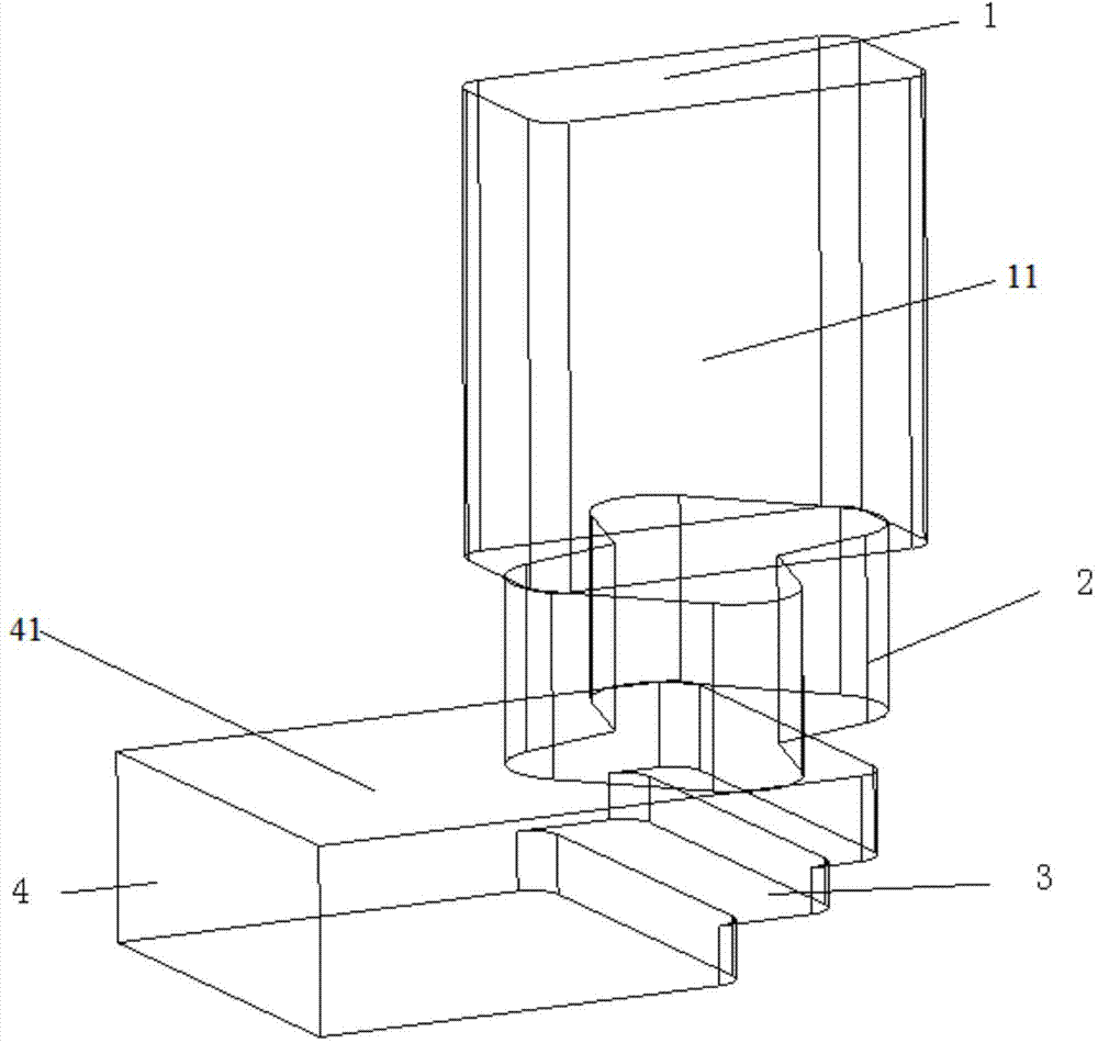
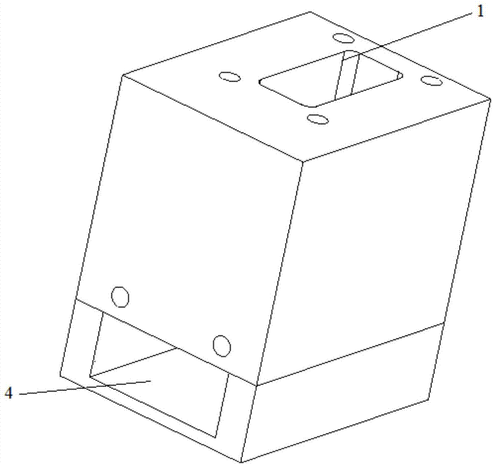
[0014] like figure 1 , 2 A 90-degree turning structure of a waveguide with polarization reversing function is shown, including a body, on which there are rectangular horizontally polarized waveguides 11 and rectangular vertically polarized waveguides 41 perpendicular to each other, and the rectangular horizontally polarized waveguides The tube 11 and the rectangular vertically polarized waveguide 41 are connected through a butterfly-shaped cavity 2 and a three-level vertical step structure 3 . The rectangular horizontally polarized waveguide port 1 and the rectangular vertically polarized waveguide port 4 are symmetrical along the center line of the body.

[0015] In order to facilitate processing, the turning structure is composed of two metal parts, the rectangular horizontally polarized waveguide 11 and the multi-level step structure 3 are processed in one part, and the rectangular vertically polarized waveguide 41 and the butterfly cavity 2 are processed inside another c...


PUM


Abstract

The invention discloses a waveguide 90-degree turning structure with the polarization turning function. The waveguide 90-degree turning structure comprises a body. A horizontal polarization waveguide channel and a perpendicular polarization waveguide channel which are perpendicular to each other are arranged on the body. The waveguide 90-degree turning structure is characterized in that the horizontal polarization waveguide channel and the perpendicular polarization waveguide channel are connected through a butterfly-shaped cavity and a multistage stepped structure. The horizontal polarization waveguide channel and the perpendicular polarization waveguide channel are rectangular waveguide pipes, and a horizontal polarization waveguide channel opening and a perpendicular polarization waveguide channel opening are symmetric about the center line of the body. The structure is formed by machining and assembling two machined metal components. The waveguide 90-degree turning structure is simple and the polarization direction and the propagation direction can be turned by 90 degrees synchronously. Waveguide openings are symmetric about the center line, consistency is well guaranteed, large-scale production is facilitated, and the waveguide 90-degree turning structure is suitable for occasions with strict requirements for the position of the waveguide pipes.

Description

technical field [0001] The invention relates to a novel waveguide device. Specifically, the component can twist the propagation direction of the microwave by 90 degrees, and can realize the twist of the polarization direction of the microwave by 90 degrees. Background technique [0002] In the electronic system where the waveguide transmits microwave signals, there are many places that need to turn 90 degrees at the same time, and the polarization direction of the electromagnetic wave needs to be reversed. In the traditional communication system, the first method is realized by a combination of a 90-degree turn on the E plane and a 90-degree turn on the H-plane; the second method is realized by using a twisted waveguide and a 90-degree turn. No matter which method is used, two components are required, which is not only bulky, high cost, and inflexible assembly; too many components will also lead to a decrease in system performance and reliability. In addition, if the twist...

Claims


Application Information

Patent Timeline
IPC IPC(8): H01P1/02
Inventor 江顺喜殷实梁国春宋永民林身平项显
Owner PIVOTONE COMM TECH
Learn More