Two-degree-of-freedom linear induction motor control method

A technology of linear induction motor and control method, which is applied in the fields of motor generator control, AC motor control, electronic commutation motor control, etc.

Active Publication Date: 2015-06-17
横川机器人(深圳)有限公司
View PDF3 Cites 4 Cited by
  • Summary
  • Abstract
  • Description
  • Claims
  • Application Information

AI Technical Summary

Problems solved by technology

However, due to the unique structure of this type of motor, a specific control method is required

Method used


Image

  • Two-degree-of-freedom linear induction motor control method
  • Two-degree-of-freedom linear induction motor control method
  • Two-degree-of-freedom linear induction motor control method

Examples


Embodiment Construction

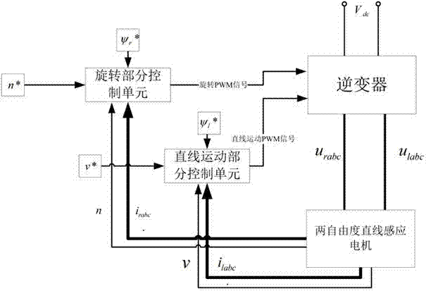
[0022] A two-degree-of-freedom linear induction motor control method mainly includes: vector control of the rotary motion part and vector control of the linear motion part, and the combination of the two makes the motor servo system achieve the purpose of stability and high precision.

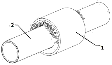
[0023] figure 1 It is the structural diagram of the two-degree-of-freedom linear induction motor, 1 is the stator of the two-degree-of-freedom direct-drive induction motor, and 2 is the motion axis of the motor.

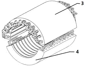
[0024] figure 2 It is the stator structure diagram of the two-degree-of-freedom linear induction motor, in which 3 is the stator of the rotating part, and 4 is the stator of the linear motion part.

[0025] When the stator winding of the rotating part of the two-degree-of-freedom linear induction motor is energized, the rotating part of the stator generates a rotating magnetic field, so that the motion shaft outputs a rotating motion. When the stator winding of the linear part of t...


PUM


Abstract

The invention relates to the field of electromechanical control, in particular to a two-degree-of-freedom linear induction motor control method used for controlling a rotating arc-shaped linear induction motor and a straight-line arc-shaped linear induction motor. According to the method, a stator current is vectorially decomposed into a current component generating a magnetic field and a current component generating torque, and the current component generating the magnetic field and the current component generating the torque are controlled respectively. Through the two-degree-of-freedom linear induction motor control method, rotating movement part vector control and linear movement part vector control are combined, sot that a motor servo system is stable and high in precision.

Description

technical field [0001] The invention relates to the field of electromechanical control, in particular to a two-degree-of-freedom linear induction motor control method for controlling a rotary arc linear induction motor and a straight arc linear induction motor. Background technique [0002] In the actual production and processing process, the drive motors of devices such as auger drilling machines, screw compressors, plastic extruders, and screw pumps all require the drive shaft to move in two degrees of freedom. The traditional technology uses multiple motors and mechanical transmission devices to realize the two-degree-of-freedom movement of the drive shaft. The solution in the traditional technology is not only complicated in control methods, but also requires a lot of expensive and bulky mechanical transmission devices. In addition, since the transmission components and bearings bear large axial force, the mechanical wear of these components is quite large, and the equip...

Claims


Application Information

Patent Timeline
Patent Type & Authority Applications(China)
IPC IPC(8): H02P21/14H02P25/06H02P27/06
Inventor 司纪凯韩俊波谢璐佳张露锋艾立旺何松许孝卓封海潮
Owner 横川机器人(深圳)有限公司
Why Eureka
Try Eureka