Clamping unit

A clamping element and clamping technology, used in clamping devices, clamping, clamps, etc., can solve the problems of hydraulic unit consumption, slow response of switching signals, etc., to achieve cost-effective, fast clamping process, accurate workpiece clamping tight effect

Inactive Publication Date: 2018-01-12
纳尔合伙有限责任公司
View PDF1 Cites 2 Cited by
  • Summary
  • Abstract
  • Description
  • Claims
  • Application Information

AI Technical Summary

Problems solved by technology

However, besides the high structural complexity, such hydraulic units have the disadvantage that they react relatively slowly to switching signals, so that they are problematic in applications in which, for reasons of productivity, for example Fast and precise movements of the clamping system are required to carry out the clamping or loosening process

Method used


Image

  • Clamping unit
  • Clamping unit
  • Clamping unit

Examples


Embodiment Construction

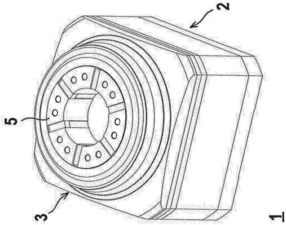
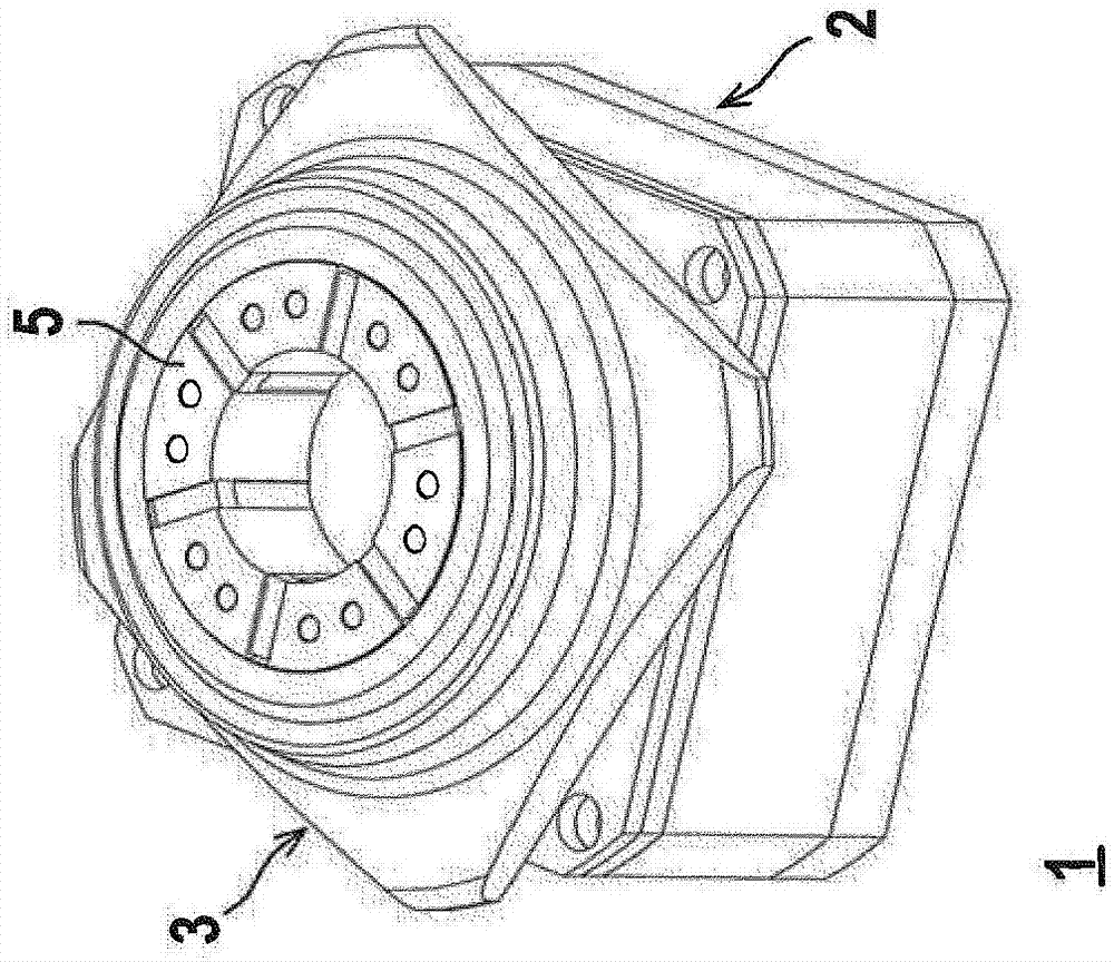
[0049] Figures 1a to 1c as well as figure 2 An exemplary embodiment of a clamping unit 1 for clamping workpieces according to the invention is shown.

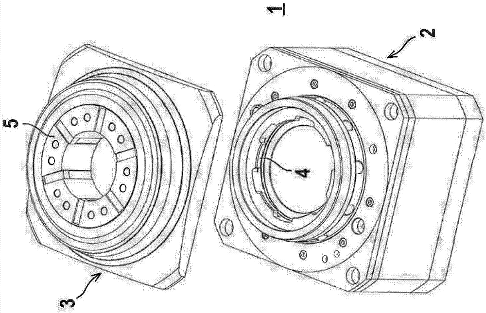
[0050] such as especially Figures 1a to 1cAs shown, the clamping unit 1 has a modular design, so that a reversibly releasable fastening of a replacement connection 3 is possible on the base module 2 . The base module 2 here forms a universal module to which different exchange connectors 3 can be fastened. The fastening of the replacement connector 3 to the base module 2 takes place by means of a bayonet lock. exist Figure 1c The locking element 4 of the bayonet lock on the base module 2 can be seen in .

[0051] Each change head 3 generally has a plurality of clamping elements 5 for clamping workpieces. The individual exchange joints 3 are distinguished from one another by the design of the clamping element 5 . exist Figures 1a to 1c In the example shown, the clamping element 5 forms a clamping head for externally c...


PUM


Abstract

A clamping unit (1) for clamping a workpiece, with an electric drive, and a gearbox unit having an arrangement of rolling elements (9). The gearbox unit is used to convert a rotary motion of an actuating element into a translational motion. By means of translational motions of the actuating element, clamping elements (5) can be moved into a clamping position in which a workpiece is clamped with clamping elements (5), and into a release position in which clamping elements (5) release the workpiece.

Description

technical field [0001] The invention relates to a clamping unit. Background technique [0002] Such clamping units are generally used for stationary clamping of workpieces in drilling and milling machines as well as machining centers and also for actuating clamping chucks for workpieces during rotary machining in lathes, grinding machines and rotary processing machines. [0003] Clamping units of the type mentioned typically have a hydraulic drive unit in order to generate the clamping force required to clamp or loosen the workpiece. However, besides the high structural complexity, such a hydraulic unit has the disadvantage that its reaction to switching signals is relatively slow, so that it is problematic in applications in which, for reasons of productivity, for example Fast and precise movements of the clamping system are required to carry out the clamping or loosening process. [0004] From DE 20 2013 101 345 U1 an electromagnetic clamping device is known which has a ...

Claims


Application Information

Patent Timeline
IPC IPC(8): B23Q3/154
CPCB23B31/28B23Q3/06B23Q17/002B23Q2703/02B23Q2703/12B23Q2717/00B25B1/106B25B1/24B25B5/10B25B5/16
Inventor H·特雷贝斯P·布罗索斯基
Owner 纳尔合伙有限责任公司
Why Eureka
Try Eureka