Drilling device and positioning assembly

A drilling device and positioning component technology, applied in the field of ships, can solve the problems of low drilling accuracy and complicated drilling equipment, and achieve the effects of improving construction efficiency, simple structure and portable operation.

Active Publication Date: 2015-06-24
武汉武船特种船艇有限责任公司
View PDF5 Cites 7 Cited by
  • Summary
  • Abstract
  • Description
  • Claims
  • Application Information

AI Technical Summary

Problems solved by technology

[0006] The invention provides a drilling device and a positioning assembly, which solves or partially solves the technical problems of low drilling precision and complicated drilling equipment in the prior art, and has the characteristics of high drilling precision, easy operation and portability

Method used


Image

  • Drilling device and positioning assembly
  • Drilling device and positioning assembly
  • Drilling device and positioning assembly

Examples


Embodiment 1

[0056] The invention provides a drilling device, which is used for drilling shell plates. Among them, according to actual operation requirements, at least one hole to be drilled is marked on the shell plate, and the marking line on the hole to be drilled completely matches the mounting hole on the steel structure to be installed correspondingly, so that the shell plate can be drilled smoothly after the drilling operation is completed. Install.

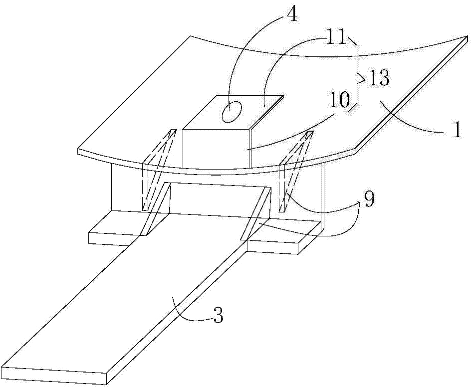
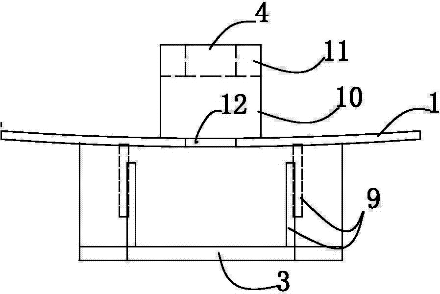
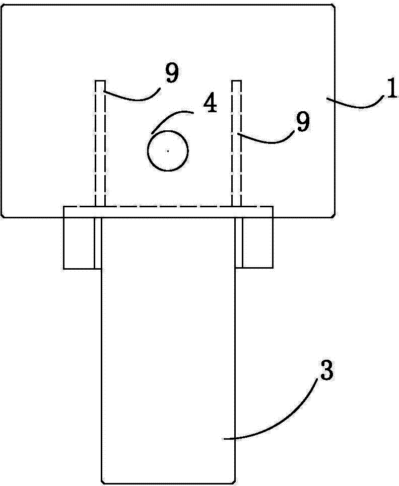
[0057] Specifically, see Figure 1-5 , The drilling device includes: a positioning component and a drilling component.

[0058] further,

[0059] The positioning assembly may at least include: a bonding plate 1 having an upper surface and a lower surface, a clamping piece 13 and a positioner 2 . Wherein, the upper surface of the bonding plate 1 is bonded to the shell plate to be drilled, and the shape and structure of the bonding plate 1 can be adaptively adjusted according to the shape and structure of the shell plate to be drilled...

Embodiment 2

[0072] Based on Embodiment 1 of the present invention, Embodiment 2 of the present invention provides a positioning assembly, including: a bonding plate, the bonding plate is bonded to the shell plate, and a first through hole is opened on the bonding plate, The first through hole is fitted correspondingly to the hole to be drilled; a clamping member, the clamping member is fixed on the bonding plate, so as to clamp the shell through the clamping member and the bonding plate plate, and a second through hole is opened on the clamping member, the second through hole is coaxially distributed with the first through hole, and the hole to be drilled is located in the first through hole, the second through hole Between the through holes; a locator, the locator is placed in the second through hole.

[0073] In Embodiment 2 of the present invention, the connection relationship, positional relationship and working principle of each component are completely the same as those in Embodimen...


PUM


Abstract

The invention discloses a drilling device and a positioning assembly. The drilling device comprises the positioning assembly. The positioning assembly comprises an attachment plate, a clamping piece, a positioner, a drilling assembly and a magnetic drill, wherein the attachment plate is attached to a shell plate and provided with a first through hole, and the first through hole is correspondingly attached to a hole to be drilled; the clamping piece is fixed to the attachment plate and provided with a second through hole; the positioner is arranged in the second through hole; the drilling assembly comprises a supporting plate, the supporting plate is fixed to the attachment plate, and the supporting plate and the clamping piece are located on the two sides of the attachment plate; the magnetic drill is fixed to the supporting plate, and a drill bit of the magnetic drill penetrates through the positioner to drill the hole to be drilled. The drilling device solves the technical problems that in the prior art, the drilling accuracy is low and a drilling device is complex, and has the advantages of being high in drilling accuracy, easy and convenient to operate and convenient to carry.

Description

technical field [0001] The invention belongs to the technical field of ships, in particular to a drilling device and a positioning component. Background technique [0002] In the prior art, for the installation of the shell (metal and non-metal), if the sample hole has been drilled on the base material, it is necessary to drill a matching installation hole on the shell, and the sample is drawn on the shell. Take a sample of the hole location, then drill the hole with a hand-held electric drill or drill press. [0003] However, for the drilling method in the prior art, there are at least the following defects: [0004] 1. For drilling with a hand-held electric drill, the drilling accuracy is not high, especially for arc-shaped shell plates, the tolerance requirements such as verticality and concentricity of the drilling cannot be guaranteed; [0005] 2. For the drilling operation of the drilling machine, the drilling equipment is complicated, the operating procedures are cu...

Claims


Application Information

Patent Timeline
IPC IPC(8): B23B45/00B23B45/14B23B49/00B23Q3/06
CPCB23B45/00B23B49/00B23Q3/062B25H1/0021
Inventor 代兆权付由庆
Owner 武汉武船特种船艇有限责任公司
Why Eureka
Try Eureka