Forming mold of indoor mutual inductor and pouring sealing method of forming mold

A technology for forming molds and transformers, applied in the manufacture of inductors/transformers/magnets, electrical components, circuits, etc., can solve the problems of secondary equipment damage to personal safety, decreased insulation, and more casting or injection abrasives, etc., to prevent Threat to personal safety, reduce unit energy consumption, and reduce the effect of mold investment

Inactive Publication Date: 2015-06-24
XUCHANG YONGXIN ELECTRIC
View PDF4 Cites 2 Cited by
  • Summary
  • Abstract
  • Description
  • Claims
  • Application Information

AI Technical Summary

Problems solved by technology

[0002] 10 kV castable current transformers are widely used in power equipment such as switch cabinets. At present, indoor 10 kV transformers are usually completed after two or more times of resin casting and sealing. Such two or more castings The results of the solid sealing method are: many pouring or injection molds are invested; the workload and intensity of work are large; the energy consumption per unit of the finished product is high; the man-hours of the finished product manufacturing unit are many; The partial discharge exceeds the standard; the joint parts of the 2 or more castings are not firmly bonded, and gaps appear, causing the joint parts to crack...

Method used


Image

  • Forming mold of indoor mutual inductor and pouring sealing method of forming mold
  • Forming mold of indoor mutual inductor and pouring sealing method of forming mold
  • Forming mold of indoor mutual inductor and pouring sealing method of forming mold

Examples


Embodiment Construction

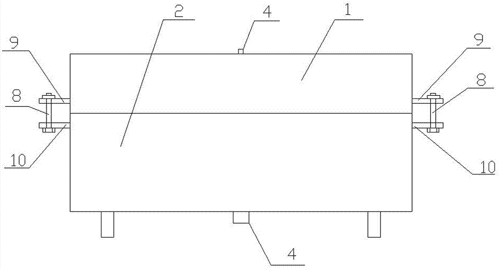
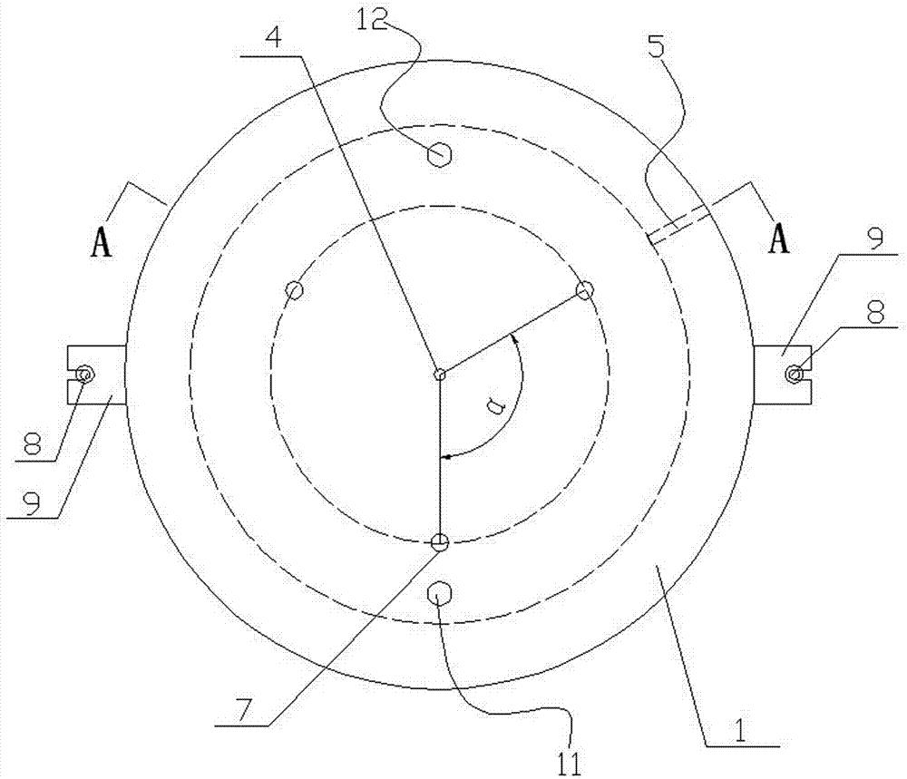
[0022] Combine below Figure 1 to Figure 5 The structure and working process of the present invention are further described.

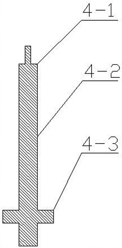
[0023] The forming mold of the indoor transformer of the present invention includes an upper mold 1 and a lower mold 2 for surrounding a mold cavity 15, and a position where the upper mold 1 and the lower mold 2 are connected is provided with a coil outlet 6 for placing the transformer. The outlet hole 5 of the upper mold 1 is provided with a pouring hole 11 and an exhaust hole 12 communicating with the mold cavity, and a mold core 4 is arranged in the mold cavity 15, and the upper and lower sides of the mold core 1 The two ends are respectively connected with the upper mold 1 and the lower mold 2, the upper end 4-1 of the mold core 4 is set in a convex shape, and the upper mold 1 is provided with a hole that matches the upper end 4-1 of the convex mold core. Upper groove 16, which is designed to separate from the mold core 4 when the upper mold 1 is ...


PUM


Abstract

The invention discloses a forming mold of an indoor mutual inductor and a pouring sealing method of the forming mold. The forming mold comprises an upper mold and a lower mold which defines a mold die cavity, wherein the upper mold is provided with a pouring hole and an exhaust hole which are communicated with the mold die cavity; a mold core is arranged in the mold die cavity, the upper end of the mold core is in the shape of Chinese character 'tu', the lower end of the mold core is in a crossed shape, and the part, positioned in the mold die cavity, of the mold core is cylindrical; a group of insulating supporting columns for supporting a mutual inductor coil is arranged around the mold core in the mold die cavity and is movably connected with the lower mold; the upper end of each insulating supporting column is provided with a step-shaped buckling platform for being buckled with the lower edge of the mutual inductor coil; and a wire outlet hole is formed in a connection position between the upper mold and the lower mold. The forming mold disclosed by the invention has the advantages that the resin pouring sealing efficiency of the indoor mutual inductor can be improved, the unit energy consumption and the rejection rate of the indoor mutual inductor are reduced, the insulating degree of the indoor mutual inductor is improved, and the indoor mutual inductor can be prevented from threatening personal safety when being broken down by high voltage.

Description

technical field [0001] The invention belongs to the technical field of manufacturing an indoor transformer, and in particular relates to a molding die for an indoor transformer and a casting and sealing method thereof. Background technique [0002] 10 kV castable current transformers are widely used in power equipment such as switch cabinets. At present, indoor 10 kV transformers are usually completed after two or more times of resin casting and sealing. Such two or more castings The results of the solid sealing method are: many pouring or injection molds are invested; the workload and intensity of work are large; the energy consumption per unit of the finished product is high; the man-hours of the finished product manufacturing unit are many; The partial discharge exceeds the standard; the joint parts of the 2 or more castings are not firmly bonded, and gaps appear, causing the joint parts to crack and reduce the insulation degree, which often causes the transformer to be b...

Claims


Application Information

Patent Timeline
IPC IPC(8): B29C39/26B29C39/10H01F41/00
Inventor 张松涛周晓默刘左锋闫志明朱志齐尚
Owner XUCHANG YONGXIN ELECTRIC
Why Eureka
Try Eureka