Train speed and range measurement system
A distance measurement system and train speed measurement technology, which is applied in the direction of railway signal and safety, can solve the problems of insufficient safety, lack of redundant data verification, etc., and achieve the effect of low difficulty in implementation, improvement of safety, and reduction of types
- Summary
- Abstract
- Description
- Claims
- Application Information
AI Technical Summary
Problems solved by technology
Method used
Image
Examples
Embodiment 1
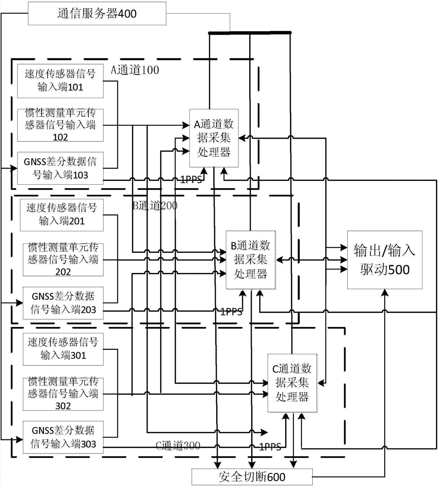
[0033] figure 1 It is a schematic structural diagram of the train speed measurement and distance measurement system provided by Embodiment 1 of the present invention.
[0034] Such as figure 1 As shown, the train speed measurement and distance measurement system provided by the present invention includes a communication server 400, three data acquisition and processing channels 100, 200, and 300 of A, B, and C respectively connected to the communication server 400, and respectively connected to the communication server 400. The safety relay 600 connected to the three data acquisition and processing channels 100, 200, and 300 of 400, A, B, and C, and the three data acquisition and processing channels 100, 200, and 300 of the safety relay 600, A, B, and C respectively The output / input drives 500.
[0035] Further, the A, B, and C data acquisition and processing channels 100, 200, and 300 all include sequentially connected data input ports, data acquisition processors, and posi...
Embodiment 2
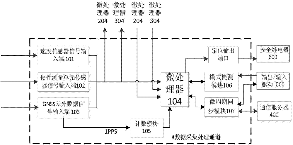
[0040] figure 2 It is a schematic diagram of data collection and processing of the data collection and processing channel 100 provided by Embodiment 2 of the present invention.
[0041] As a preferred mode of the above-mentioned embodiment, further, the data acquisition processors of the data acquisition and processing channels 100, 200, and 300 of the A, B, and C all include a microprocessor and a counting module connected to it, a microcycle synchronization module, a mode detection module. Wherein, the GNSS differential data signal input terminal is connected to the counting module; the mode detection module and the microcycle synchronization module are connected to the output / input driver; the microcycle synchronization module is connected to the communication server through Ethernet Connection: The signal input end of the speed sensor and the sensor signal input end of the inertial measurement unit are respectively connected to the microprocessors of the three data acqui...
Embodiment 3
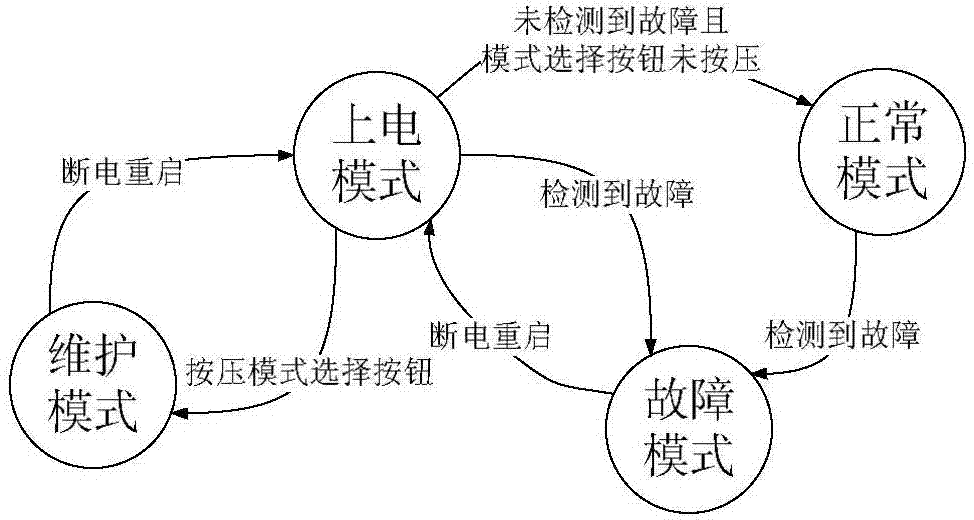
[0045] image 3 It is a mode state transition diagram of the microprocessor of the data acquisition and processing channel of the present invention;
[0046] Figure 4 It is a microcycle synchronous schematic diagram of the power-on mode of the microprocessor of the data acquisition and processing channel of the present invention and the communication host;
[0047] Figure 6 It is a schematic diagram of the distribution of microcycles in the normal mode of the microprocessor of the data acquisition and processing channel of the present invention;
[0048] Figure 8 It is a schematic diagram of microcycle synchronization in normal mode between microprocessors of data acquisition and processing channels in the present invention.
[0049] Further, the microcycle synchronization module includes a power-on startup unit, a self-check unit, an initial synchronization unit, a normal synchronization unit, a data fusion unit, a synchronization comparison unit, a map matching unit, an...
PUM
 Abstract
Description
Claims
Application Information
 - R&D
- Intellectual Property
- Life Sciences
- Materials
- Tech Scout
- Unparalleled Data Quality
- Higher Quality Content
- 60% Fewer Hallucinations
Browse by: Latest US Patents, China's latest patents, Technical Efficacy Thesaurus, Application Domain, Technology Topic, Popular Technical Reports.
© 2025 PatSnap. All rights reserved.Legal|Privacy policy|Modern Slavery Act Transparency Statement|Sitemap|About US| Contact US: help@patsnap.com


