Bilge well for ship

A technology for sewage wells and ships, which is used in the direction of pipelines, hulls, and ship parts for emptying/ballasting, and can solve problems such as difficult dismantling, large manufacturing processes, and complexity, and achieves convenient installation, maintenance, and disassembly, and shortens working hours , the effect of improving efficiency

Active Publication Date: 2015-06-24
SHANGHAI SHIPYARD
View PDF8 Cites 1 Cited by
  • Summary
  • Abstract
  • Description
  • Claims
  • Application Information

AI Technical Summary

Problems solved by technology

[0003] The technical problem to be solved by the present invention is to overcome the disadvantages of the prior art that the installation process is relatively large and the production process is complicated and difficult to dismantle, and to provide a sewage well for ships that is flexible in volume setting, simple in manufacturing process, and easy to transform.

Method used


Image

  • Bilge well for ship
  • Bilge well for ship
  • Bilge well for ship

Examples


Embodiment 1

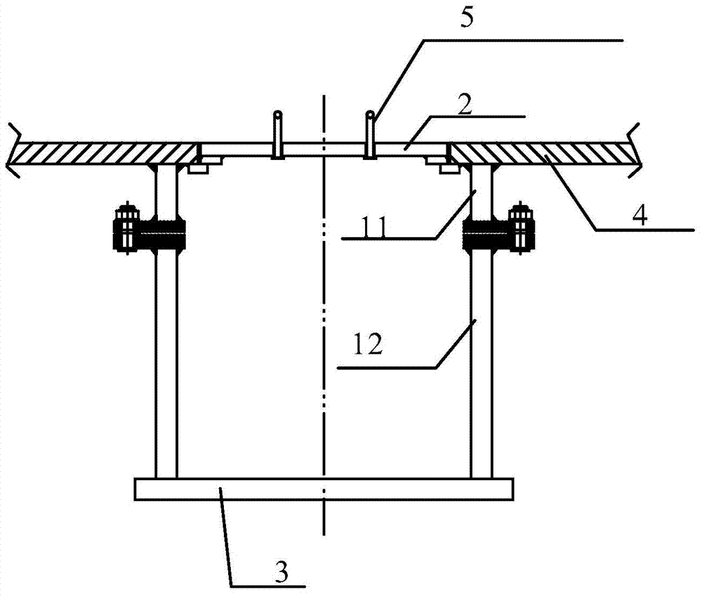
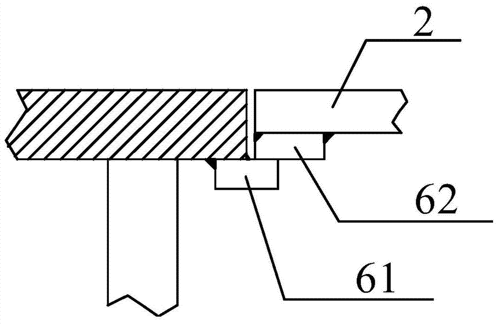
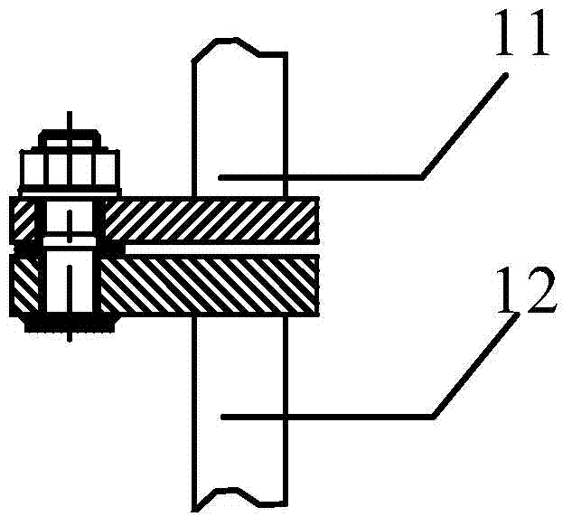
[0029] figure 1 It is a structural schematic diagram of a section of a sewage well for a ship in this embodiment, figure 2 It is a schematic diagram of the connection structure between the well body and the bilge of the present embodiment, image 3 It is a schematic diagram of the connection structure of the upper well body and the lower well body of the present embodiment, as Figure 1~3 As shown, the sewage well for ships involved in this embodiment includes an upper well body 11, a lower well body 12, a well cover 2 and a well floor 3, and the upper well body 11 and the lower well body 12 are cylindrical steel pipes with the same diameter. The lower end of the body 11 and the outer circumference of the upper end of the lower well body 12 are welded with wings, and these wings are fixed by bolts so that the upper well body 11 and the lower well body 12 are fixed.

[0030] The lower well body 12 and the well bottom plate 3 are welded and combined in the workshop first, and...

Embodiment 2

[0036] Figure 4 It is a structural schematic diagram of a section of a sewage well for a ship according to Embodiment 2 of the present invention, Figure 5 It is a schematic diagram of the connection structure between the upper well body and the bilge of Embodiment 2 of the present invention, as Figure 4~5 As shown, the difference between this embodiment and Embodiment 1 is that the outer periphery of the upper end of the upper well body 11 is welded to the bilge 4, and the inner circumference of the upper end of the upper well body 11 is ring-shaped with several pads 63, and the pads 63 Used to support manhole cover 2.

Embodiment 3

[0038] Figure 6 It is the structural representation of the cross-section of the sewage well used for ships of the present embodiment, as Figure 6 As shown, the difference between this embodiment and Embodiment 2 lies in that the upper well body 11 and the lower well body 12 are connected and fixed with their axes forming an obtuse angle.

[0039] This embodiment can better solve the problem of limited construction space.


PUM


Abstract

The invention discloses a bilge well for a ship. The bilge well for the ship comprises a well body and a well bottom plate which are integrally welded. A well cover covers the upper end of the well body. The well body is spliced by an upper well body and a lower well body. The upper and lower well bodies are cylinder-shaped steel pipes and are fixedly connected in a threaded manner. The well body, the well cover and the well bottom plate are prefabricated according to set sizes and are assembled in a cabin. An opening is formed in the bottom of the cabin. The upper end of the well body is welded with the bottom of the cabin. The diameter of the upper opening of the well body is larger than the inner diameter of the opening. The lower end of the well body is welded with the well bottom plate. The bilge well has the advantages that the manufacturing process of the bilge well is simplified by designing the well body into the cylindrical shape; labor hour is shortened and the efficiency is improved by prefabricating the bilge well and field splicing; the bilge well is convenient to mount, maintain and demount and widely applicable by the threaded connection; the bilge well is applicable to special working space by using the oblique lower well body.

Description

technical field [0001] The invention relates to a sewage well, in particular to a sewage well for ships. Background technique [0002] At present, marine sewage wells are generally operated on-site, and the materials are spliced ​​and welded on site. After the ship is launched, such a scheme needs to be installed on the outer plate below the side waterline, and the operation accuracy is very high. In addition, the existing marine sewage wells are usually in the shape of a square box, so the installation volume is relatively large, and the manufacturing process is relatively complicated. For example, the workload of welding operations will be very large. And it requires a wide space for work and installation. The existing square box-shaped sewage well is connected to the main body on multiple sides, and the plate thickness of the main body surface needs to be increased additionally. In addition, it is difficult to dismantle the sewage well due to all welded connections durin...

Claims


Application Information

Patent Timeline
Patent Type & Authority Applications(China)
IPC IPC(8): B63B13/00
Inventor 周青春宋国强杨宏伟张成杰张婷
Owner SHANGHAI SHIPYARD
Why Eureka
Try Eureka