
A compound sand-retaining wall capable of forming longitudinal spiral flow to retain and discharge sand

A technology of spiral flow and sand retaining wall, applied in the field of compound sand retaining wall, can solve the problems of low sand retaining efficiency, loss of function, serious sediment deposition, etc. Ease of construction

Active Publication Date: 2017-09-29
SICHUAN UNIV
View PDF5 Cites 2 Cited by
  • Summary
  • Abstract
  • Description
  • Claims
  • Application Information

AI Technical Summary

Problems solved by technology

However, when the amount of sand carried by the incoming flow is large, the following two prominent problems are often encountered: (1) The newly-built sand retaining wall has a better effect of retaining sand, but after a period of operation, the mass will gradually submerge the sand retaining wall, causing The sand-blocking efficiency of the sand-blocking wall is reduced. In severe cases, the sand-blocking wall will be completely submerged, making it useless, and a large amount of sand will enter the water intake
During the operation period of a hydropower station in Yunnan Province from 2008 to 2010, because the anti-sand flushing measures arranged in front of the water intake of the first hub did not achieve the preset effect, the front pool of the water intake and the reservoir section in front of the sluice were seriously silted up. Even manual dredging before the water intake gate is far from guaranteeing normal water intake for power generation
(2) Even if the distance between the moving mass and the sand-blocking wall is controlled by opening the sand discharge, some coarse particles will still be carried by the water flow into the water intake, that is, the sand-blocking efficiency needs to be improved

Method used


Image

  • A compound sand-retaining wall capable of forming longitudinal spiral flow to retain and discharge sand
  • A compound sand-retaining wall capable of forming longitudinal spiral flow to retain and discharge sand
  • A compound sand-retaining wall capable of forming longitudinal spiral flow to retain and discharge sand

Examples


Embodiment Construction

[0025] The present invention will be described in detail below in conjunction with specific embodiments. It should be noted that the technical features or combinations of technical features described in the following embodiments should not be regarded as isolated, and they can be combined with each other to achieve better technical effects.

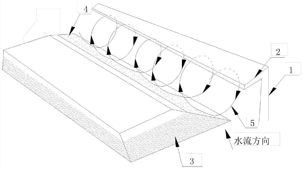
[0026] figure 1 Shown is a schematic diagram of the structure of the compound sand-blocking wall of the present invention and its principle of sand-blocking and sand-discharging;

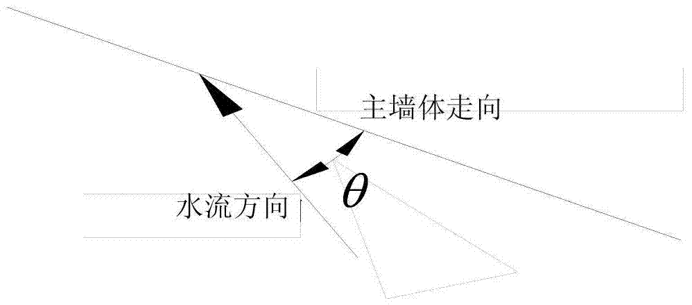
[0027] figure 2 Shown is a schematic diagram of the included angle formed by the direction of the main wall of the compound sand retaining wall of the present invention and the direction of water flow;

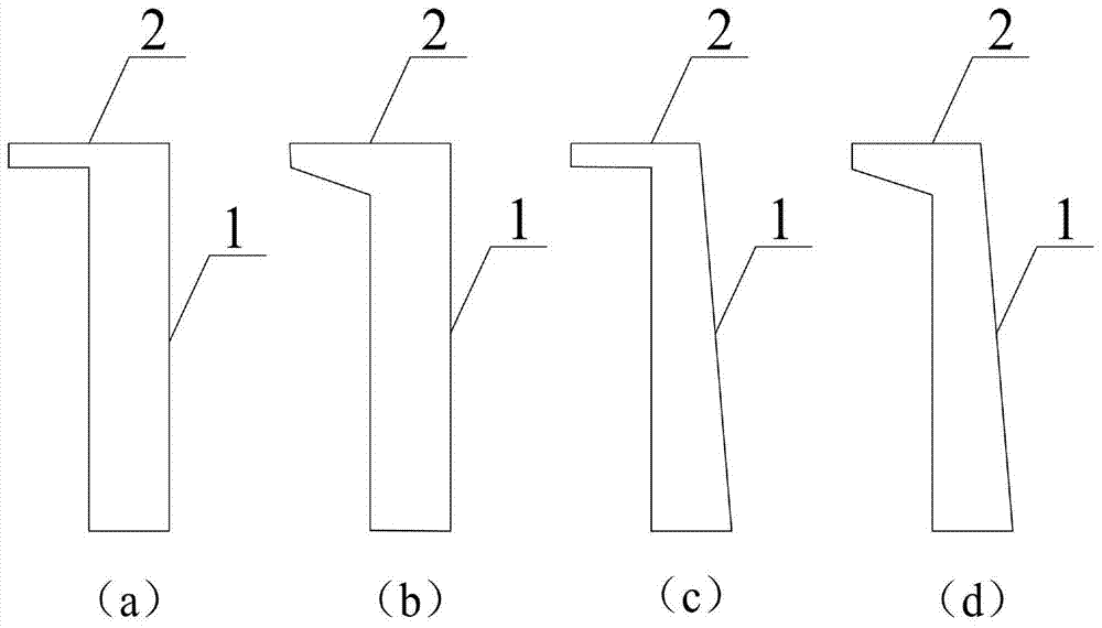
[0028] image 3 Shown is the cross-sectional schematic view of the compound sand retaining wall of the present invention.

[0029] Such as figure 1 with figure 2 As shown, a compound sand-blocking wall capable of forming longitudinal spiral flow sand-bl...


PUM


Abstract

The invention provides a compound sand-blocking wall capable of forming longitudinal spiral flow for sand-blocking and sand-discharging. angle. The invention can effectively intercept the drifting sediment, and the water flow can form a spiral flow outside the sand-blocking wall to start and transport the deposited drifting sediment downstream, preventing the drifting head from approaching the sand-blocking wall. It is economical and efficient without additional sand removal measures. The problem of sand retention and sand discharge of the low-head diversion hydropower station is effectively solved.

Description

technical field [0001] The invention belongs to the technical field of sand-blocking and sand-discharging in water conservancy and hydropower irrigation and water diversion projects, and in particular relates to a compound sand-blocking wall capable of forming longitudinal spiral flow for sand-blocking and sand-discharging. Background technique [0002] In water conservancy irrigation, water intake projects or water diversion projects for hydropower generation, the problem of water intake and sand control often determines the success or failure of the project. For a long time, relevant foreign and domestic experts have carried out in-depth research on scientific, feasible and economical sand retention and sand removal measures, such as artificial bend type, bottom grid type, layered type and other water intake and sand discharge facilities, curved sand sedimentation Pools and other types of sand sinking facilities. [0003] Kolesnikov of the former Soviet Union designed the...

Claims


Application Information

Patent Timeline
Patent Type & Authority Patents(China)
IPC IPC(8): E02B3/02
CPCE02B8/023E02B9/04Y02E10/20
Inventor 张法星邓军刘善均许唯临田忠王韦张建民曲景学
Owner SICHUAN UNIV
Learn More