Thermally and/or mechanically actuated component wall of a fluid and/or gas-conveying component, in particular a cylinder head of a combustion engine

A mechanical load, internal combustion engine technology applied in the field of component walls to achieve the effect of reducing costs

Active Publication Date: 2015-06-24
MAN NUTZFAHRZEUGE AG
View PDF7 Cites 1 Cited by
  • Summary
  • Abstract
  • Description
  • Claims
  • Application Information

AI Technical Summary

Problems solved by technology

This can cause thermal problems in the area of ​​the surface of the cylinder

Method used


Image

  • Thermally and/or mechanically actuated component wall of a fluid and/or gas-conveying component, in particular a cylinder head of a combustion engine
  • Thermally and/or mechanically actuated component wall of a fluid and/or gas-conveying component, in particular a cylinder head of a combustion engine
  • Thermally and/or mechanically actuated component wall of a fluid and/or gas-conveying component, in particular a cylinder head of a combustion engine

Examples


Embodiment Construction

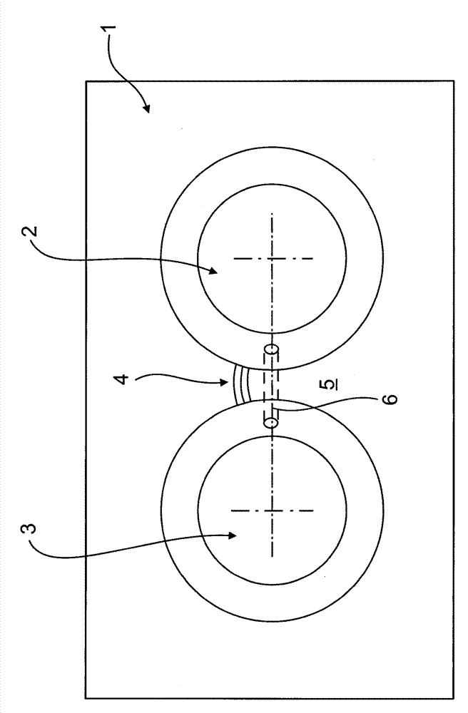
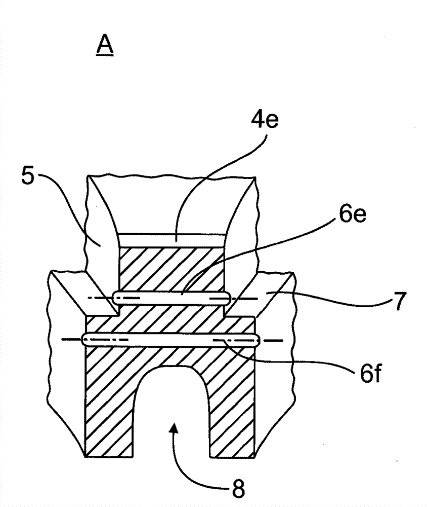
[0042] exist figure 1 A plan view of a partial area of ​​a cylinder head 1 of an internal combustion engine is shown in the area of ​​two adjacent valve seats 2 , 3 . As a crack initiation, a notch 4 is provided on the upper side of the bridging wall 5 , wherein the notch 4 is shifted a little relative to the smallest valve seat distance. Bore 6 runs as a crack stop parallel to the bridge wall surface in bridge wall 5 as connection of valve seats 2 , 3 below the cutout. For better visibility, the valve seats in all figures are shown without seat rings.

[0043] figure 2 A second alternative arrangement of the combination of crack initiation and crack arrestors is shown:

[0044] to this end, figure 2 A perspective plan view of a partial region of a four-valve cylinder head 1 with four valve seats 3 a , 3 b , 3 c , 3 d is shown. Here, compared to figure 1 The notches 4 a , 4 b , 4 c , 4 d are respectively arranged as crack initiations in the valve bridging region with t...


PUM


Abstract

The invention relates to thermally and/or mechanically actuated component wall of a fluid and/or gas-conveying component, in particular a cylinder head of a combustion engine. The component wall is provided with at least one area which is threated from cracking due to load, wherein the crack is formed in the component wall (5) from the outer side of the wall under the operating condition; and at least one crack prevention part (6), which is arranged in a crack extending part and prevents the crack from expanding, and especially traverses through the component wall (5) to expand to important component area (8). According to the invention, in the areas (5, 10) threathened by cracks, the outer side of the wall is provided with a crack starting part (4), which prevents the forming and expanding of cracks which are not under control.

Description

technical field [0001] The invention relates to a thermally and / or mechanically loaded component wall of a fluid-conducting and / or gas-conducting component, in particular a cylinder head, of an internal combustion engine according to the preamble of claim 1 . Background technique [0002] It is known that component walls of fluid-conducting or gas-conducting components, which are subjected to thermal or thermodynamic loads, tend to crack. The tendency to cracking can be mitigated in a manner known per se by solid structures and / or expansion joints and / or reduced temperature loading. However, especially in motor construction, these measures can only be used conditionally: the solid construction type is strictly limited due to the weight and cost situation. Likewise, the thermal load cannot be reduced practically, since the operation-related combustion in the internal combustion engine takes place at very high temperatures for thermodynamic reasons. The very high specific po...

Claims


Application Information

Patent Timeline
IPC IPC(8): F02F1/36B22D19/00
CPCF02F1/24F02F2001/248
Inventor H.米勒
Owner MAN NUTZFAHRZEUGE AG
Why Eureka
Try Eureka