Braking device for vehicle

A braking device and vehicle technology, applied in the field of vehicles, can solve the problems of difficulty in the allocation of design space, short replacement cycle, and high requirements for machining accuracy of parts, so as to save frame space, save maintenance costs, and save vehicle layout. handy effect

Active Publication Date: 2015-06-24
CRRC QISHUYAN INSTITUTE CO LTD
View PDF5 Cites 14 Cited by
  • Summary
  • Abstract
  • Description
  • Claims
  • Application Information

AI Technical Summary

Problems solved by technology

Caliper disc brakes occupy most of the market due to their low price and relatively stable braking performance. The increase of the increase brings difficulties to the distribution of the installation space of the vehicle chassis, and the friction area of ​​the friction pair of the caliper disc brake is relatively small, the friction plate wears quickly, and the replacement cycle is short, resulting in increased maintenance and use costs
The full-disc multi-disc wet brake has a long service life and strong adaptability to the environment. Its multi-disc structure is easy to realize serialization and requires less installation space. However, this type of brake has a complex structure and relatively small piston shaft and diameter, which makes it easy for the piston to get stuck. hysteresis, and require high machining accuracy for parts with matching relationships, and high manufacturing costs. In addition, the friction pair adopts forced oil cooling, which increases the additional supporting hydraulic system and cost. It is often only used in brakes with high maintenance-free requirements. On high-end engineering vehicles
[0003] In addition, in the various brake systems used in vehicles, automobiles and engineering vehicles, the service brake and the parking brake are arranged separately, so they need their own independent installation space, and the layout of the corresponding pipelines and other accessories is therefore more complicated. When designing a compact vehicle, direct reference to the above prior art will inevitably lead to difficult or even impossible design space allocation

Method used


Image

  • Braking device for vehicle
  • Braking device for vehicle
  • Braking device for vehicle

Examples


Embodiment 1

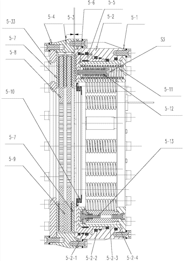
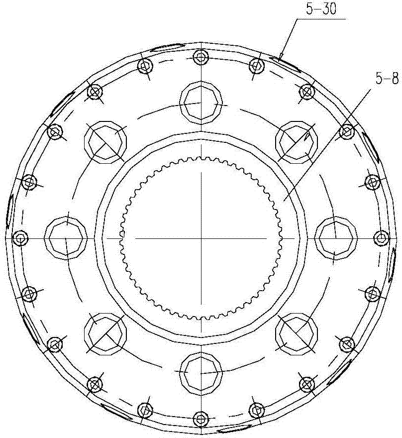
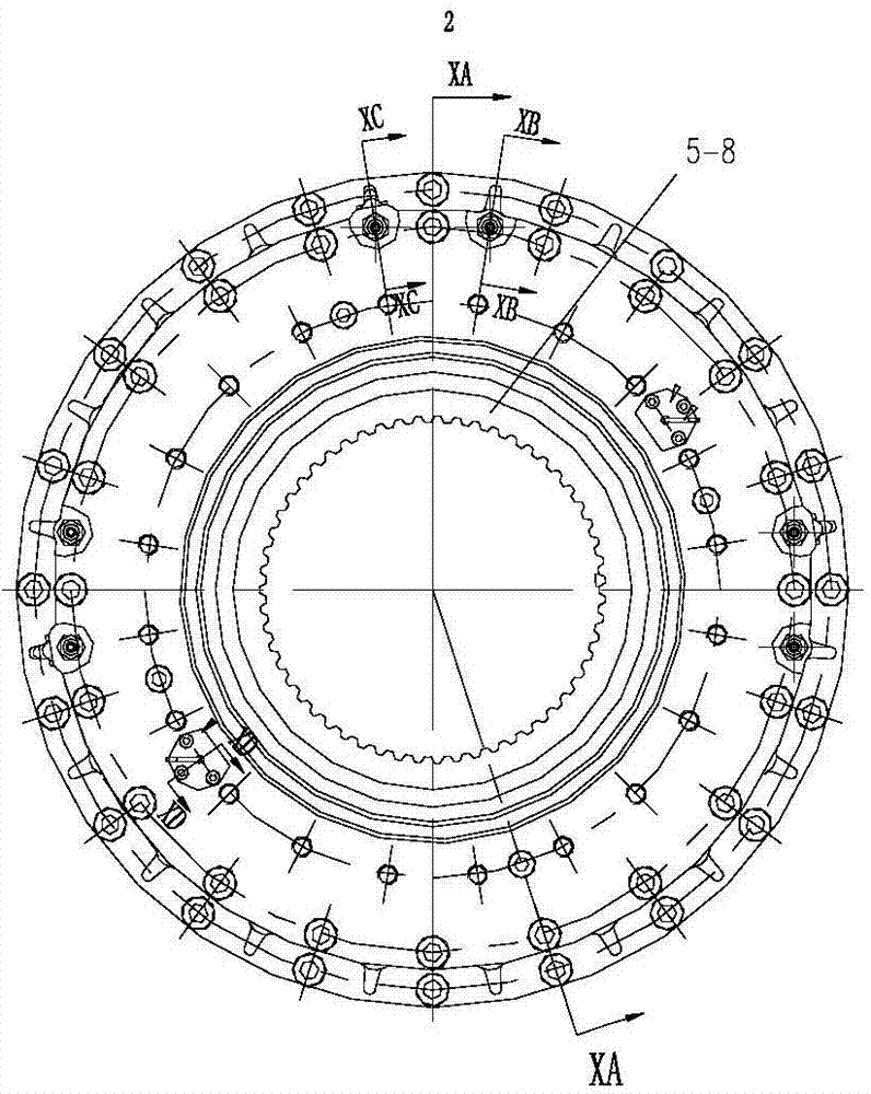
[0020] The vehicle braking device of this embodiment is as figure 1 , 2 , 3, including a group of three outer circles distributed at intervals and the inner hole of the circular intermediate body 5-3 constrained by the spline structure in the circumferential direction and axially constitute the friction plates 5-7, 5-9 of the moving pair, wherein 5-7 are single-sided friction plates with friction layers located inside both ends, and 5-9 are double-sided friction plates with friction layers located on both sides in the middle. A brake disc 5-8 is installed between adjacent friction plates, the inner hole of the brake disc 5-8 and the power output shaft are constrained in the circumferential direction by the inner spline and constitutes a moving pair in the axial direction, and the friction plate and the brake disc form a friction vice. One end of the friction pair is installed with a friction plate end cover 5-4 fixedly connected with the intermediate body 5-3, and the other ...


PUM


Abstract

The invention relates to a braking device for a vehicle and belongs to the technical field of vehicles. A braking disk is arranged between every two adjacent friction sheets of the brake so that a friction pair can be formed; an oil cylinder block is provided with an axial oil cylinder hole, a hollow driving piston with a step outer circle is installed in the large-diameter segment and the diameter-shrinkage segment of the oil cylinder hole, and the driving piston and an annular cavity formed at the diameter changing position between the large-diameter segment and the diameter-shrinkage segment form a driving braking oil cylinder; a parking piston is installed in the isolation segment and the diameter-enlarging segment, and the parking piston and an annular cavity at the diameter changing position between the isolation segment and the diameter-enlarging segment form a parking braking oil cylinder; parking springs are distributed in the parking piston in the circumferential direction in a spaced mode, return springs pressed and held by the pressing and holding end of return bolts are installed in the parking springs, and the ends, far away from the pressing and holding ends, of the return bolts penetrate through the bottom of the parking piston and are fixedly connected with the driving piston. According to the braking device, space is made full use of, the structure is very compact, the thermal load capacity of the friction sheets can be improved easily, service life is remarkably prolonged, and the braking device is very suitable for flexible configuration of various vehicles with narrow design spaces.

Description

technical field [0001] The invention relates to a braking device, in particular to a vehicle braking device, which belongs to the technical field of vehicles. Background technique [0002] As far as the applicant knows, traditional automobiles and engineering vehicles mostly use caliper disc brakes or full-disk multi-plate wet brakes. Caliper disc brakes occupy most of the market due to their low price and relatively stable braking performance. However, under the premise of the same power source, the improvement of braking capacity can only be achieved by increasing the braking radius, while the size The increase of the increase brings difficulties to the distribution of the installation space of the vehicle chassis, and the friction area of ​​the friction pair of the caliper disc brake is relatively small, the friction plate wears quickly, and the replacement cycle is short, resulting in increased maintenance and use costs. The full-disc multi-disc wet brake has a long ser...

Claims


Application Information

Patent Timeline
Patent Type & Authority Applications(China)
IPC IPC(8): F16D55/224F16D65/14F16D65/40F16D121/04F16D125/06F16D125/08
Inventor 陈学伟高雷李艳红王村伟宫峰郑剑云
Owner CRRC QISHUYAN INSTITUTE CO LTD
Why Eureka
Try Eureka