Capacitive sensor electrode
A capacitive sensor and electrode technology, which is applied in the direction of capacitance measurement, using electric/magnetic devices to transmit sensing components, instruments, etc., can solve the problems of reduced detection sensitivity and insufficient detection sensitivity of mutual capacitance capacitance sensors, etc., to improve detection The effect of sensitivity
- Summary
- Abstract
- Description
- Claims
- Application Information
AI Technical Summary
Problems solved by technology
Method used
Image

Examples
no. 1 approach
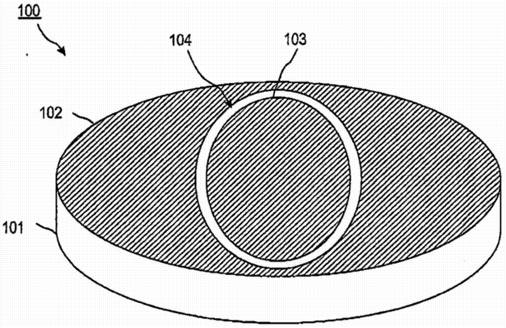
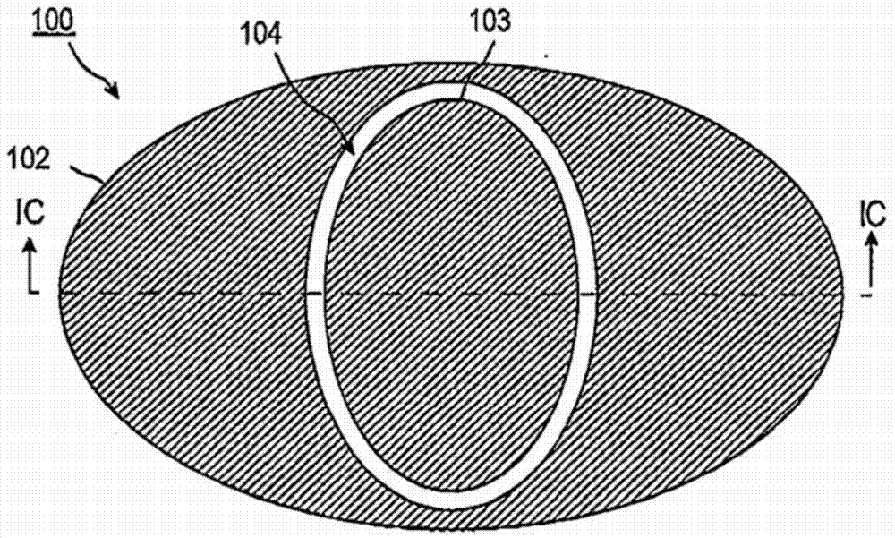
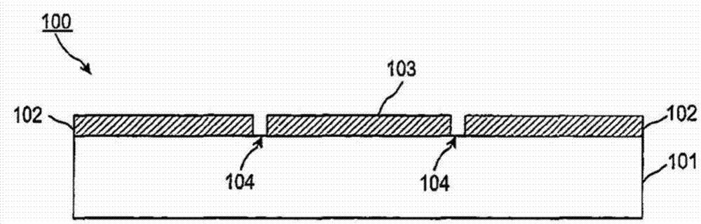
[0049] Figure 1A , Figure 1B and Figure 1C The structure of the capacitive sensor electrode according to the first embodiment disclosed herein is shown. Figure 1A is a perspective view of a capacitive sensor electrode, Figure 1B is the plan view of the capacitive sensor electrodes, and Figure 1C is along Figure 1B A cross-sectional view taken of the IC-IC wire.
[0050]The capacitive sensor electrode 100 includes a transmitting electrode 102 as a first electrode and a receiving electrode 103 as a second electrode, and both the transmitting electrode 102 and the receiving electrode 103 are disposed on the main surface of the substrate 101 . The substrate 101 is an insulating substrate and may be formed of, for example, resin or glass. The transmitting electrode 102 and the receiving electrode 103 are provided on the same main surface of the substrate 101 . The transmitting electrode 102 and the receiving electrode 103 are formed of, for example, conductive metal. T...
no. 2 approach
[0091] The capacitive sensor electrode according to the second embodiment disclosed herein includes a ground electrode disposed near the transmission electrode with a gap placed between the transmission electrode and the ground electrode, as described above in Figure 10A to Figure 10C The case of the simulation model described in . When the ground electrode is provided near the transmission electrode, the lines of electric force spreading toward the vicinity of the capacitive sensor electrode are absorbed by the ground electrode and do not diffuse to the vicinity of the capacitive sensor electrode. Therefore, when an object formed of a conductive material approaches the capacitive sensor electrode, the distribution of electric force lines generated from the transmitting electrode changes and the problem of erroneous detection can be prevented.
no. 3 approach
[0093] Figure 14 A capacitive sensor electrode according to a third embodiment disclosed herein is shown. Figure 14 is showing the capacitive sensor electrodes along with the Figure 1B The cross section of the IC-IC line corresponds to the cross section taken and shows the Figure 1C A diagram of a modified example of the configuration of . Figure 14 The illustrated capacitive sensor electrode 1400 includes a transmit electrode 1402 and a receive electrode 1403 disposed on a major surface of a substrate 1401, and also includes a ground electrode 1405 disposed on the other major surface opposite to the one described above (in the following referred to in the text as "back"). Preferably, the ground electrode 1405 is arranged such that at least a part of the transmitting electrode 1402 and the receiving electrode 1403 is opposite to the ground electrode 1405, wherein the substrate 1401 is placed between at least a part of the transmitting electrode 1402 and the receiving e...
PUM
 Abstract
Description
Claims
Application Information
 - R&D Engineer
- R&D Manager
- IP Professional
- Industry Leading Data Capabilities
- Powerful AI technology
- Patent DNA Extraction
Browse by: Latest US Patents, China's latest patents, Technical Efficacy Thesaurus, Application Domain, Technology Topic.
© 2024 PatSnap. All rights reserved.Legal|Privacy policy|Modern Slavery Act Transparency Statement|Sitemap