

Dual-redundancy control method and system of brushless motor
A control method, brushless motor technology, applied in control systems, electronic commutation motor control, single motor speed/torque control, etc. judgment, the effect of improving reliability
- Summary
- Abstract
- Description
- Claims
- Application Information
AI Technical Summary
Problems solved by technology
Method used
Image

Examples
Embodiment 1
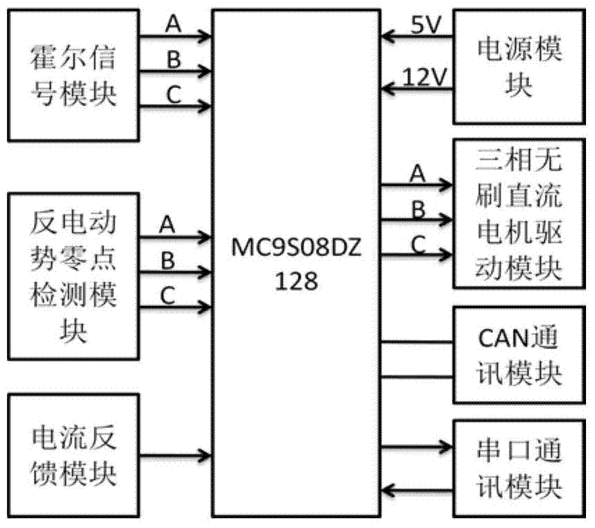
[0057] The dual redundancy control system of the brushless motor in this embodiment is as follows figure 1 As shown, the Hall signal module and the back-EMF zero-crossing detection module obtain the motor phase, and use the three-phase brushless DC motor drive module to realize the commutation control of the motor. When the Hall position sensor is working normally, the system uses the Hall sensor position signal to control the motor commutation; when the Hall signal is abnormal, the system can immediately find and replace it with the back EMF position signal to ensure that it continues to operate and improve the motor performance. reliability.
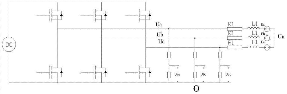
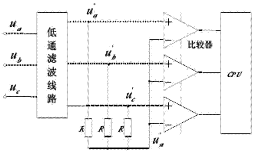
[0058] For the above-mentioned detection of the zero-crossing point of the back-EMF, the terminal voltage method of constructing a simulated neutral point can be used to detect the zero-crossing point of the back-EMF. figure 2 The terminal voltage method is based on the principle of the back EMF detection circuit. The terminal voltag...
Embodiment 2
[0068] Since the sensor signal may be disturbed and deviated during the operation of the motor, this does not mean that the sensor is faulty. If it is just a simple threshold judgment, misjudgment is likely to occur.
[0069] Therefore on the basis of embodiment 1, carry out further improvement:
[0070] (1) Monitor in real time whether the position signal output by the position sensor exceeds the predetermined threshold; if it does not exceed the predetermined threshold, the position signal output by the position sensor is used for output;
[0071] (2) If the predetermined threshold is exceeded, timing;
[0072] (3) Monitoring, within a predetermined time, whether the position signal output by the position sensor continues to exceed the predetermined threshold;
[0073] (4) if exceeding the predetermined time, the position signal output by the position sensor still continues to exceed the predetermined threshold value, then adopt the position signal calculated by the control...
Embodiment 3
[0076] In order to ensure the accuracy and stability of fault judgment, a set of fault confirmation mechanisms must be adopted on the basis of Example 2, such as Figure 8 shown. The entire fault confirmation mechanism is divided into four states: intact, quasi-failure, final failure, and quasi-good.
[0077] When a fault is reported by the system, the timing of the fault acknowledgement time will start, and the fault will be regarded as a quasi-fault. When the fault confirmation timer exceeds the set fault confirmation time, the fault is regarded as the final fault.
[0078] During this process, if the fault confirmation timer has not exceeded the set fault confirmation time, but the fault phenomenon has disappeared, the fault state will transition from quasi-fault to intact. In the same way, for a confirmed final fault, when the system no longer detects the fault phenomenon, if the fault integrity timer exceeds the set integrity confirmation time, the fault state at this t...
PUM
 Abstract
Description
Claims
Application Information