Through substrate via inductors

A technology of inductors and glass substrates, which is applied in the field of inductors and can solve problems such as dissipating energy

Inactive Publication Date: 2015-06-24
SNAPTRACK
View PDF6 Cites 10 Cited by
  • Summary
  • Abstract
  • Description
  • Claims
  • Application Information

AI Technical Summary

Problems solved by technology

Real inductors have a finite quality factor (Q), meaning that in addition to storing energy

Method used


Image

  • Through substrate via inductors
  • Through substrate via inductors
  • Through substrate via inductors

Examples


Embodiment Construction

[0053] The following description is directed to certain embodiments for the purpose of describing the innovative aspects of the invention. However, those skilled in the art will readily recognize that the teachings herein can be applied in many different ways. The described embodiments can be implemented in any device, apparatus, or system that can be configured to display an image, whether in motion (e.g., video) or stationary (e.g., still image), and whether the image is text , graphic or pictorial. Rather, it is contemplated that the described implementations may be included in or associated with a variety of electronic devices such as, but not limited to, a mobile phone , cellular phones with multimedia Internet capabilities, mobile television receivers, wireless devices, smart phones, Devices, Personal Data Assistants (PDAs), Wireless Email Receivers, Handheld or Laptop Computers, Netbooks, Notebook Computers, Smartbooks, Tablet Computers, Printers, Copiers, Scanners, ...


PUM


Abstract

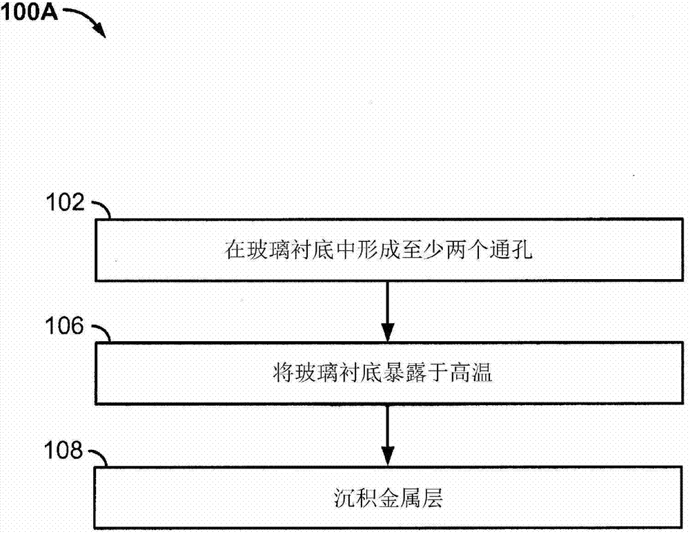
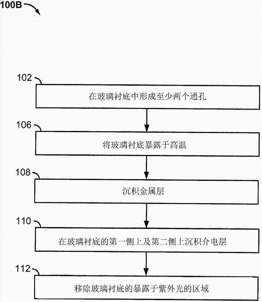
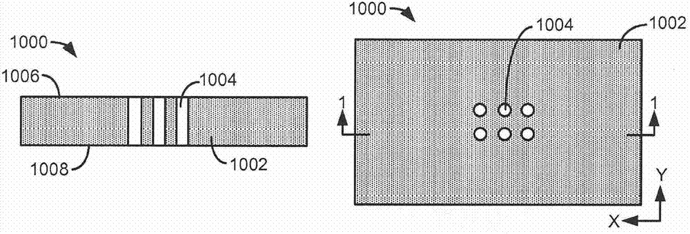
This disclosure provides systems, methods, and apparatus for through substrate via inductors. In one aspect, a cavity is defined in a glass substrate. At least two metal bars are in the cavity. A first end of each metal bar is proximate a first surface of the substrate, and a second end of each metal bar is proximate a second surface of the substrate. A metal trace connects a first metal bar and a second metal bar. In some instances, one or more dielectric layers can be disposed on surfaces of the substrate. In some instances, the metal bars and the metal trace define an inductor. The inductor can have a degree of flexibility corresponding to a variable inductance. Metal turns can be arranged in a solenoidal or toroidal configuration. The toroidal inductor can have tapered traces and/or thermal ground planes. Transformers and resonator circuitry can be realized.

Description

[0001] priority information [0002] This application is claimed in co-pending Application No. 1, entitled THROUGH SUBSTRATE VIA INDUCTORS, filed Oct. 16, 2012, by Shenoy et al. (Attorney Docket No. QUALP155A / 121830U1) Priority to US Patent Application Serial No. 13 / 653,132, which is hereby incorporated by reference in its entirety for all purposes. technical field [0003] The present invention relates generally to inductors, and more particularly to through substrate via inductors. Background technique [0004] Electromechanical systems (EMS) include devices with electrical and mechanical elements, such as transducers such as sensors and actuators, optical components such as mirrors and optical films, and electronics. EMS devices or elements can be fabricated on a variety of scales, including but not limited to microscale and nanoscale. For example, microelectromechanical systems (MEMS) devices may include structures ranging in size from about one micron to hundreds of ...

Claims


Application Information

Patent Timeline
IPC IPC(8): H01F17/00H01F41/04
CPCH01F17/0033H01F41/046Y10T156/1057Y10T29/49165H01F41/041G09G3/3466G09G5/00H01F21/00H01F27/06H01F41/005
Inventor 拉温德拉·V·社诺伊日塔伊·基姆赖关余乔恩·布拉德利·拉斯特菲利普·贾森·斯蒂法诺唐纳德·威廉·基德韦尔叶夫根尼·彼得罗维奇·古塞夫
Owner SNAPTRACK
Why Eureka
Try Eureka