
Self-powered electronic retina

A retinal, self-powered technology, applied in the direction of eye implants, etc., can solve the problems of blind people's inconvenience, coil heating, etc., and achieve the effect of small size

Inactive Publication Date: 2015-07-01
SECOND MILITARY MEDICAL UNIV OF THE PEOPLES LIBERATION ARMY
View PDF8 Cites 0 Cited by
  • Summary
  • Abstract
  • Description
  • Claims
  • Application Information

AI Technical Summary

Problems solved by technology

The existing power supply device is to place a receiving coil under the skin of the head, and wirelessly power it through an external power supply coil. The problem with this method is that the coil will heat up after a long time of power supply
In addition, even if a rechargeable battery is installed inside the human body to save the electric energy of the coil, it also needs to be charged every once in a while, which is very inconvenient for the blind

Method used


Image

  • Self-powered electronic retina
  • Self-powered electronic retina
  • Self-powered electronic retina

Examples


Embodiment 1

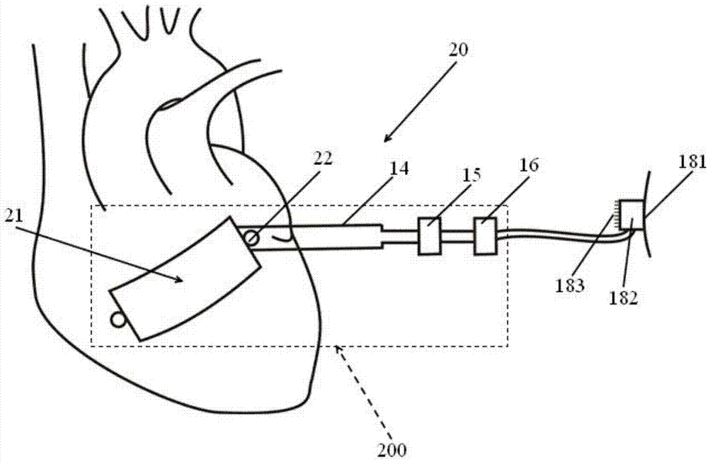
[0026] figure 1 It is a schematic diagram in which the power generation body of the self-powered electronic retina in Example 1 is a quadrilateral, such as figure 1 As shown, the self-powered electronic retina 20 has a power generation unit 200 , a photosensitive unit 181 , a signal processing unit 182 , and a stimulating electrode 183 . Wherein, the power generating unit 200 includes a power generating body 21 , an electric energy storage unit 16 , a fixing unit 22 and an output unit, and the output unit has an output electrode 14 and a rectification and filtering circuit 15 .

[0027] The generating body 21 is rectangular, and has a fixing unit 22 on each of the two narrow sides of the rectangle, which is used to fix the generating body 11 on the epicardium in the long axis direction along the systolic direction. The fixing unit 22 is composed of an encapsulation layer, and there is no power generation structure such as electrodes or piezoelectric materials inside the fixin...

Embodiment 2

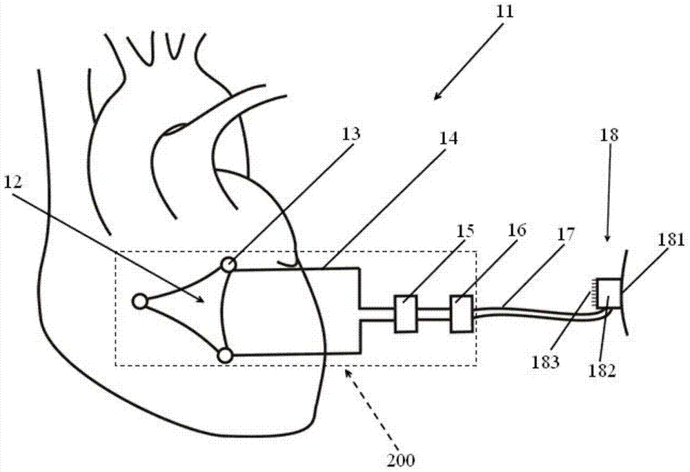
[0032] image 3 It is a schematic diagram of a self-powered electronic retina in which the power generation part is a triangle in an embodiment of the present invention, as image 3 As shown, the power generation main body 12 of the self-powered electronic retina 11 of the present invention is a triangle, and each apex position of the triangle has a fixed unit 13, and the output electrode 14 is connected with the electrode layer (see figure 2 ), the rectification and filtering circuit 15 is connected to the output electrode 14 , and the electric energy storage unit 16 is connected to the rectification and filtering circuit 15 to store the electric energy generated by the power generation unit.

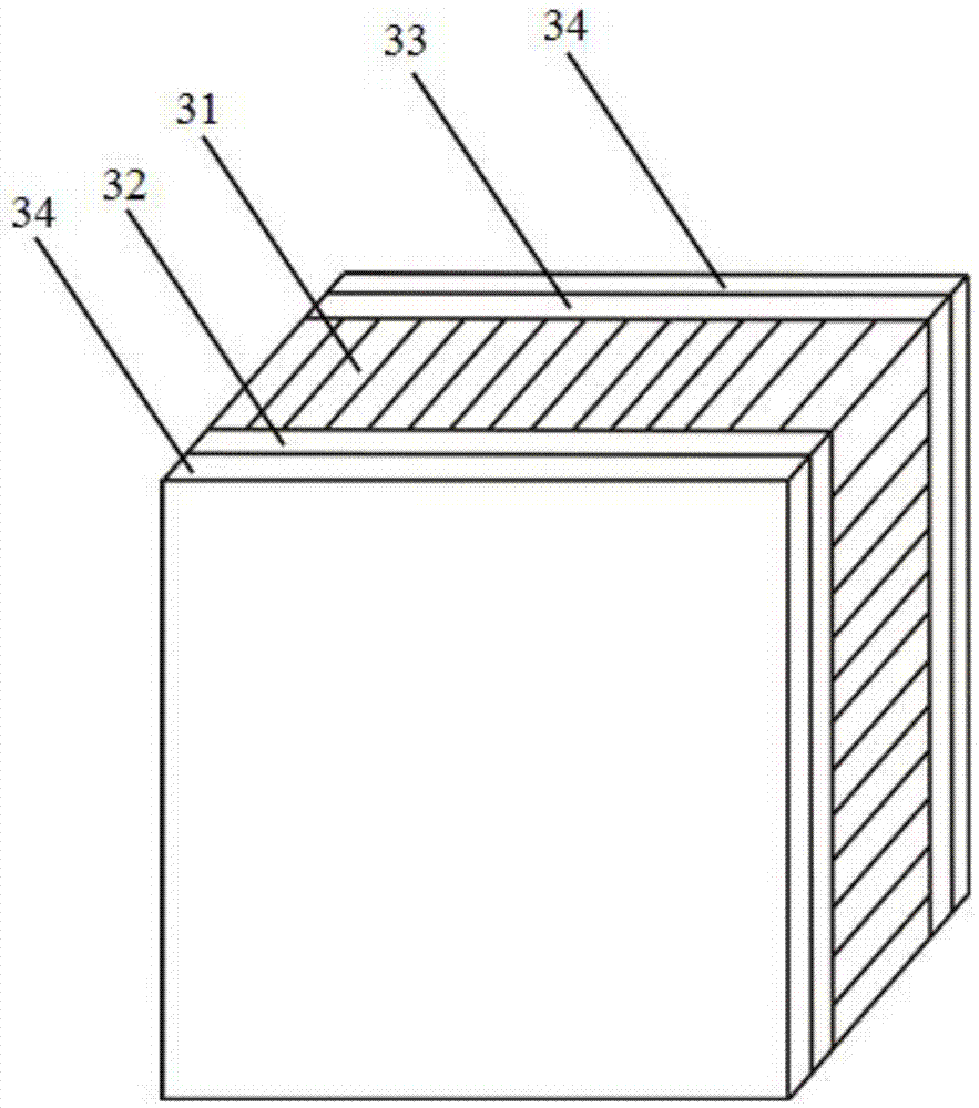
[0033] figure 2 is a cross-sectional view of the self-powered electronic retina of the embodiment of the present invention, such as figure 2 As shown, the central layer of the power generation body 12 is a piezoelectric material layer 31, and the piezoelectric material layer 31 is...


PUM


Abstract

The invention provides a self-powered electronic retina. The self-powered electronic retina is characterized by comprising a photosensitive unit, a signal processing unit, a stimulating electrode and a power generation unit. The power generation unit comprises a power generation body, an output unit, an electrical energy storage unit, a fixing unit and an encapsulation layer. The power generation body is of a multilayer film structure and comprises a piezoelectric material layer arranged on the center of the power generation body and electrode layers arranged on both sides of the piezoelectric material layer. The output unit is connected to the electrode layers to output the current generated by the power generation body to the electrical energy storage unit. The electrical energy storage unit is used for storing electrical energy and supplying the signal processing unit and the stimulating electrode with power. The fixing unit is arranged on the edge of the power generation body and used for fixing the power generation body to the epicardium. The encapsulation layer covers the surfaces of the power generation body, the output unit, the electrical energy storage unit and the fixing unit. The self-powered electronic retina needs no battery replacement and can achieve lifetime use.

Description

technical field [0001] The invention relates to a self-powered electronic retina, which belongs to the field of medical equipment. Background technique [0002] There are many kinds of eye diseases that cause human vision loss. If the loss of vision is caused by the lens, the purpose of restoring vision can be achieved by replacing the new lens through surgery. However, if the vision loss or even blindness is caused by retinopathy, simple Surgical operations are impotent. In this case, if the patient only has retinal lesions and the optic nerve is still intact, the electronic retina can be used to improve vision. Electronic eyes currently entering the clinical trial stage usually have a photosensitive part, a microprocessor and stimulating electrodes. Since the electronic retina needs to be implanted in the human eye, the location is special, so the choice of its power supply device must be very careful. The existing power supply device is to place a receiving coil under ...

Claims


Application Information

Patent Timeline
Patent Type & Authority Applications(China)
IPC IPC(8): A61F2/14
Inventor 张浩曲丹郎希龙徐志云
Owner SECOND MILITARY MEDICAL UNIV OF THE PEOPLES LIBERATION ARMY
Learn More