Iron tower material corrector

A technology of orthotics and tower materials, which is applied in the field of orthotics for iron towers and towers, can solve problems such as equipment safety and operation safety hazards, poor performance, and difficulty in restoring the original shape of iron tower main materials, so as to improve the scope of operability and improve Job completion rate and manpower saving effect

Inactive Publication Date: 2015-07-01
LIAOYANG POWER SUPPLY COMPANY OF STATE GRID LIAONING ELECTRIC POWER SUPPLY +1
View PDF8 Cites 2 Cited by
  • Summary
  • Abstract
  • Description
  • Claims
  • Application Information

AI Technical Summary

Problems solved by technology

[0002] When traditional transmission line towers are damaged by external forces and the tower materials are excessively deformed, most of them use methods such as pulling, pushing, smashing, and warping to correct them or disassemble and flatten the damaged tower materials and then install them back to their original positions. Since there are no special tools Most of the effects are not good, especially if the main material of the iron tower is damaged, it is more difficult to restore the original shape, which poses a huge safety hazard to equipment safety and operation safety

Method used


Image

  • Iron tower material corrector
  • Iron tower material corrector

Examples


Embodiment 1

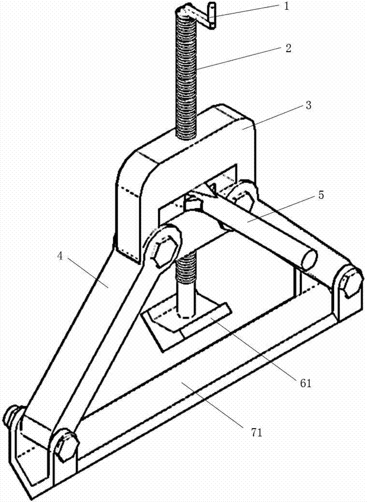
[0013] like figure 1 As shown, the iron tower tower material corrector includes: lead screw crank handle 1, elastic screw 2, main load-bearing platform 3, load-bearing bracket 4, correction terminal and support bracket, and the main load-bearing platform as a whole is Square to carry the primary springback force from the orthotic terminals. The middle part of the upper and lower beams of the main load-bearing platform has a through hole, and the bottom end of the elastic screw 2 passes through the through hole from top to bottom and is connected with the correction terminal, and the elastic lead screw is used to transmit the thrust to the correction terminal.

[0014] A lead screw handle 1 is installed on the top of the elastic lead screw 2, and the lead screw is rotated by the lead screw handle to quickly adjust and correct the desired position of the terminal before being stressed.

[0015] There are two load-bearing brackets 4, the top of the load-bearing bracket is connec...

Embodiment 2

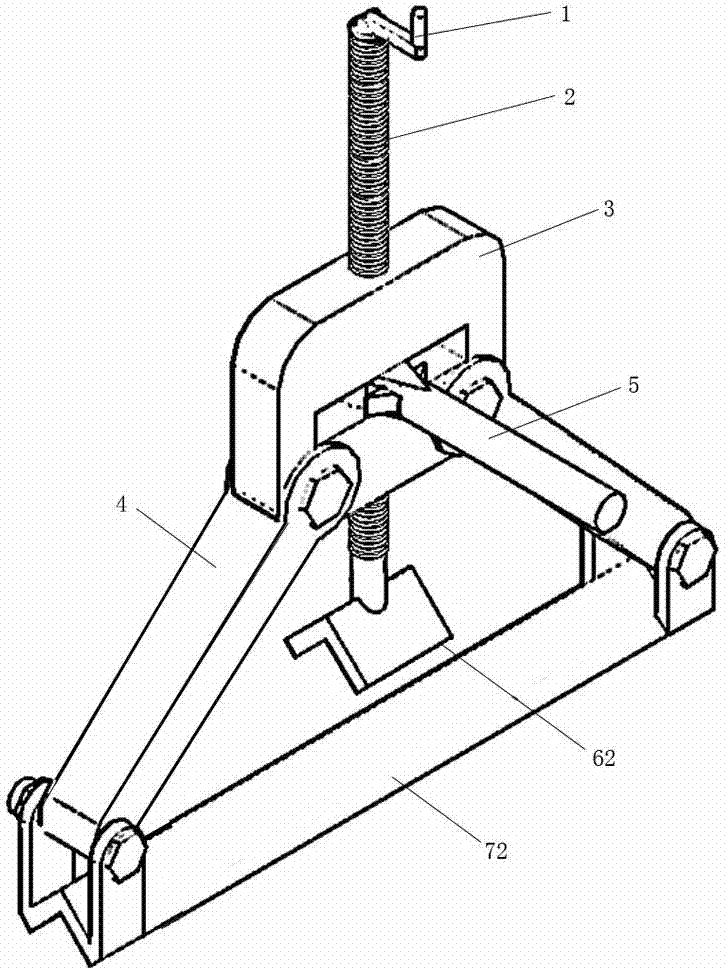
[0018] like figure 2 As shown, the iron tower tower material corrector includes: lead screw crank handle 1, elastic screw 2, main load-bearing platform 3, load-bearing bracket 4, correction terminal and support bracket, and the main load-bearing platform as a whole is Square to carry the primary springback force from the orthotic terminals. The middle part of the upper and lower beams of the main load-bearing platform has a through hole, and the bottom end of the elastic screw 2 passes through the through hole from top to bottom and is connected with the correction terminal, and the elastic lead screw is used to transmit the thrust to the correction terminal.

[0019] A lead screw handle 1 is installed on the top of the elastic lead screw 2, and the lead screw is rotated by the lead screw handle to quickly adjust and correct the desired position of the terminal before being stressed.

[0020] There are two load-bearing brackets 4, the top of the load-bearing bracket is conne...


PUM


Abstract

The invention relates to an iron tower material corrector which comprises a lead screw crank, a tightness adjusting lead screw, a main force bearing platform, force bearing supports, a correction terminal and a bearing bracket. The whole main force bearing platform is square. Through holes are formed in the middle portions of an upper beam and a lower beam of the main force bearing platform. The bottom end of the tightness adjusting lead screw penetrates through the through hole from top to bottom and is then connected with the correction terminal. The lead screw crank is installed at the top end of the tightness adjusting lead screw. The top ends of the two force bearing supports are connected with the main force bearing platform. The bottom ends of the force bearing supports are connected with the bearing bracket. A tightness adjusting lead screw handle is installed on the tightness adjusting lead screw. Due to the arrangement of the main force bearing platform, the tightness adjusting lead screw and the correction terminal which can stretch and retract and are located on the same straight line, the force opposite to that of the bearing bracket is generated, a deformed tower material can be effectively corrected, the original shape and the original angle of the tower material can be restored, and compared with a traditional method, the iron tower material corrector is more effective and the restoration degree is closer to the design standard. The iron tower material corrector is suitable for all tower shapes and high in universality.

Description

technical field [0001] The invention relates to an iron tower and tower material corrector used for sorting and repairing tower materials on site when a power transmission line tower is damaged by external force. Background technique [0002] When traditional transmission line towers are damaged by external forces and the tower materials are excessively deformed, most of them use methods such as pulling, pushing, smashing, and warping to correct them or disassemble and flatten the damaged tower materials and then install them back to their original positions. Since there are no special tools Most of the effects are not good, especially if the main material of the iron tower is damaged, it is more difficult to restore the original shape, which poses a huge safety hazard to equipment safety and operation safety. Contents of the invention [0003] The technical problem to be solved by the present invention is to provide a power transmission line iron tower tower material ...

Claims


Application Information

Patent Timeline
Patent Type & Authority Applications(China)
IPC IPC(8): B21D3/00
CPCB21D3/16
Inventor 张森张宏宇高洪波雷宏阳陆尧李煜潼王雷赵军薛丽敏尚勇王军婷
Owner LIAOYANG POWER SUPPLY COMPANY OF STATE GRID LIAONING ELECTRIC POWER SUPPLY
Why Eureka
Try Eureka