
Alternative moisture and temperature resistant forming tubes

a technology of forming tubes and moisture resistance, applied in the field of forming tubes, can solve the problems of insufficient flexibility or durable reuse of existing paperboard forming tubes, inability to use at high speeds, and inability to achieve high-speed glass fiber formation, etc., and achieve the effect of cost-effectiveness

Inactive Publication Date: 2006-02-09
DAIMLER AG +1
View PDF39 Cites 3 Cited by
  • Summary
  • Abstract
  • Description
  • Claims
  • Application Information

AI Technical Summary

Benefits of technology

[0005] Forming tubes are typically helically wound tubes of three or more kraft paper plies in which each ply includes a spiral butt joint. Those having ordinary skill in the art will understand that a spiral butt joint describes a configuration in which strips of paper are wound edge to edge. The spiral butt joints in contiguous layers are typically staggered to enhance strength.
[0013] Accordingly, it is an object of the present invention to provide a cost-effective forming tube for use and reuse in the manufacture of glass fibers.
[0014] It is a further object of the present invention to provide a paperboard forming tube having outstanding moisture resistance.
[0015] It is a further object of the present invention to provide a paperboard forming tube having excellent temperature resistance.
[0016] It is a further object of the present invention to provide a moisture-resistant and temperature-resistant tube that is collapsible but that can recover its original shape.

Problems solved by technology

Problems occur, however, in the formation of glass fiber using devices that operate at higher speeds (e.g., 7,000 RPM).
Existing paperboard forming tubes have been unusable at high speeds because increased centrifugal forces cause them to rupture.
Existing forming tubes may be bendable to facilitate removal from fiberglass spools, but have not been sufficiently flexible or sufficiently durable to reuse.
Forming tubes designed to overcome this problem are often so expensive that it is more cost effective to employ single-use forming tubes than known reusable forming tubes.
This disclosed tube, however, is not used under the severe conditions required for fiberglass manufacture (i.e., sprayed with an aqueous solution and heated to high temperatures for extended periods).

Method used

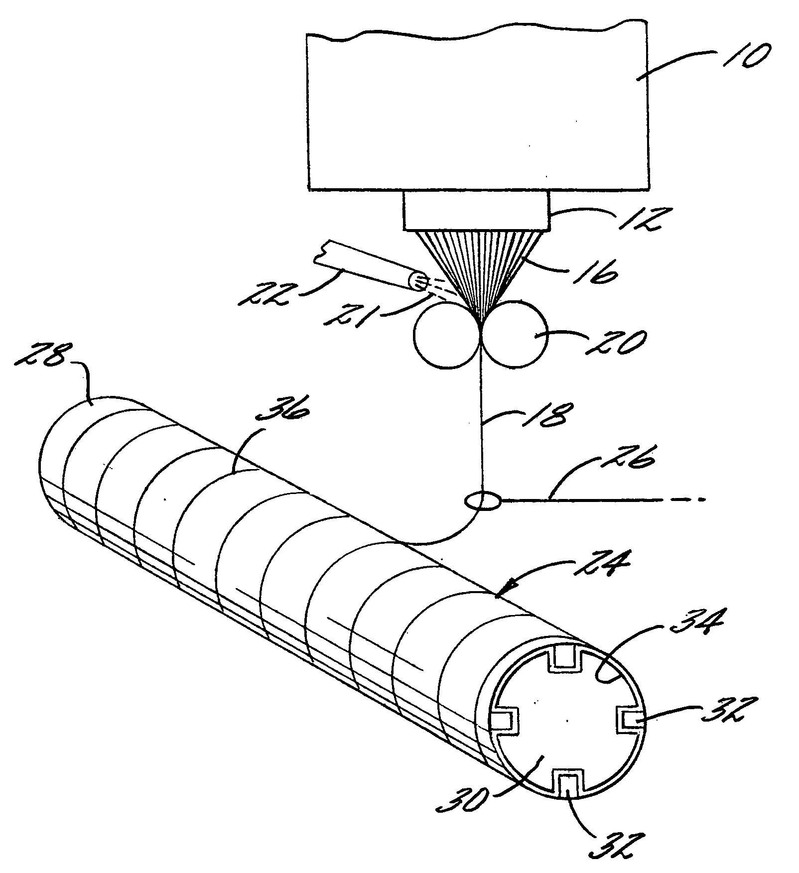
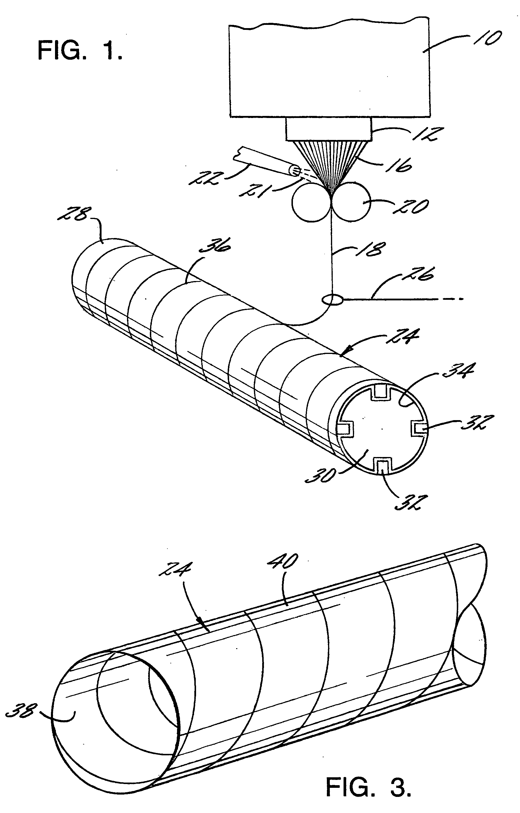
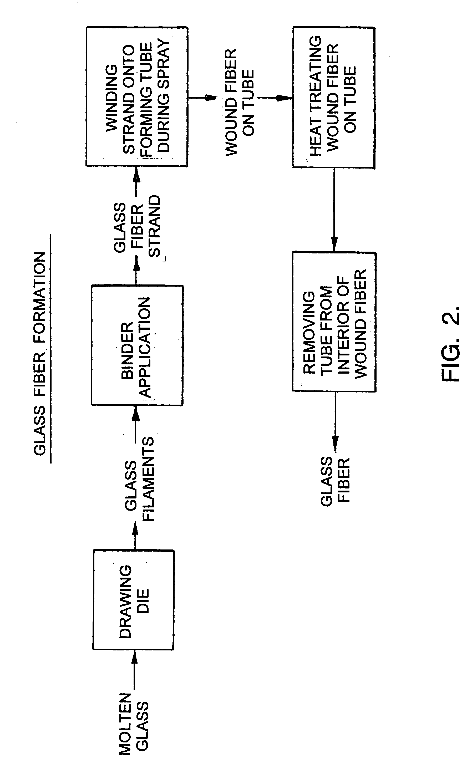

Image

  • Alternative moisture and temperature resistant forming tubes
  • Alternative moisture and temperature resistant forming tubes
  • Alternative moisture and temperature resistant forming tubes

Examples


Embodiment Construction

[0023] In one aspect, the invention is a collapsible tube having excellent moisture and temperature resistance.

[0024] As set forth herein, the collapsible tube preferably includes a fibrous structure, such as a spirally wound or convolute paperboard structure. The collapsible tube further includes moisture-resistant and temperature-resistant layers at its inside surface and outside surface. As set forth herein, these moisture-resistant and temperature-resistant layers typically include polymeric, parchment, or metallic materials, and are preferably metal foil layers. Although the collapsible tube is typically a substantially cylindrical structure, it can be made in other shapes, too.

[0025] In another aspect, the invention is a method of making such forming tubes.

[0026] In yet another aspect, the invention is a method of using such forming tubes in the manufacture of glass filaments.

[0027] An appreciation of the present invention may be achieved by reviewing typical methods for m...


PUM

PropertyMeasurementUnit
Temperatureaaaaaaaaaa
Structureaaaaaaaaaa

Abstract

The invention is a collapsible tube having excellent moisture and temperature-resistance. The collapsible tube, such as a spirally wound or convolute paperboard forming tube, includes moisture-resistant and temperature-resistant layers at its inside and outside surfaces. These moisture-resistant and temperature-resistant layers may be polymeric, parchment, or metallic materials, particularly metal foil layers. The collapsible tube is especially useful as a reusable forming tube in the manufacture of glass fibers.

Description

BACKGROUND OF THE INVENTION [0001] This application hereby claims the benefit of the following commonly-assigned provisional patent applications: U.S. Provisional Patent Application Ser. No. 60 / 598,317, for Moisture and Temperature Resistant Forming Tubes, filed Aug. 3, 2004; U.S. Provisional Patent Application Ser. No. 60 / 659,530, for Alternative Moisture and Temperature Resistant Forming Tubes, filed Mar. 8, 2005; and U.S. Provisional Patent Application Ser. No. 60 / 695,566, for Alternative Moisture and Temperature Resistant Forming Tubes, filed Jun. 30, 2005. This application incorporates entirely by reference these provisional applications.[0002] The present invention relates to forming tubes that are especially useful in processes for forming glass fiber. [0003] In this regard, the process of making glass fiber involves the winding of a hot glass fiber around a fast-rotating forming tube. After winding to form a fiberglass spool, the glass fiber is further processed at elevated ...

Claims


Application Information

Patent Timeline
IPC IPC(8): B32B27/10B29C33/50
CPCB31C1/00Y10T428/1303B32B3/266B32B7/005B32B15/02B32B15/12B32B15/18B32B15/20B32B27/08B32B27/12B32B27/32B32B27/34B32B27/365B32B29/00B32B29/02B32B29/06B32B2250/03B32B2250/40B32B2255/10B32B2255/26B32B2307/306B32B2307/748B32B2597/00B65H75/10B65H2701/31C03B37/03B32B1/08B32B7/03
Inventor TKACIK, PETER T.PARTIN, DAVID A.SWEATMAN, JOEL G.RUSSELL, JIMMY A.
Owner DAIMLER AG
Learn More