Electric pneumatic coupled pressure foot of automatic drilling tail end executor and control method

An end effector and pneumatic coupling technology, which is applied in the direction of manufacturing tools, drilling/drilling equipment, boring machine/drilling machine parts, etc., can solve the problems of affecting the quality of hole making, damaging the workpiece, increasing the pressing force, etc., to achieve The effect of simple and compact structure, avoiding co-action, and high pressure accuracy

Active Publication Date: 2015-07-01
NANJING UNIV OF AERONAUTICS & ASTRONAUTICS +1
View PDF5 Cites 3 Cited by
  • Summary
  • Abstract
  • Description
  • Claims
  • Application Information

AI Technical Summary

Problems solved by technology

[0005] (1) The feed pressure of the independent cylinder is unstable, and the compaction state during hole making cannot be adjusted, so that the compaction force increases with the spindle feed, which affects the processing quality;
[0006] (2) The independent motor drive has no buffering and overload protection functions, and cannot guarantee the stability when adjusting the pressing force, which affects the quality of hole making and damages the workpiece in severe cases;
[0007] (3) The independent operation of the pressure foot and the spindle system increases the force acting on the workpiece, and fluctuates with the fluctuation of the hole-making force, which affects the hole-making stability of the system

Method used


Image

  • Electric pneumatic coupled pressure foot of automatic drilling tail end executor and control method
  • Electric pneumatic coupled pressure foot of automatic drilling tail end executor and control method

Examples


Embodiment Construction

[0025] The present invention will be further described below in conjunction with accompanying drawing:

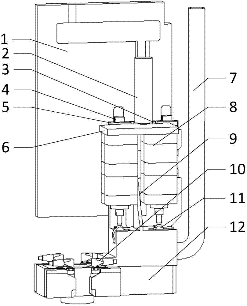
[0026] Such as figure 1 The pressure foot of the electro-pneumatic coupling of the automatic hole-making end effector shown is installed on the spindle base plate 1, the hole-making spindle is installed on the spindle base plate 1, and the spindle base plate 1 is installed on the internal cross slide of the end effector, and the hole is made The main shaft is fed with the movement of the main shaft bottom plate 1 on the cross slide. The pressure foot includes a pressure foot body and a pressure foot servo system. The pressure foot body is connected to the pressure foot base 12. The pressure foot servo system includes a servo motor 2 and a drive cylinder 8 1. The upper computer that controls the servo motor 2 and the drive cylinder 8, the upper computer is installed on the end effector controller, the servo motor 2 drives the ball screw, the first screw connecting plate 6 is...


PUM


Abstract

An electric pneumatic coupled pressure foot of an automatic drilling tail end executor is installed on a spindle base plate, wherein a drilling spindle is installed on the spindle base plate, the spindle base plate is installed on an internal cross sliding table of the tail end executor, and the drilling spindle performs feed with movements of the spindle base plate on the cross sliding table. The electric pneumatic coupled pressure foot is characterized in that the pressure foot comprises a pressure foot body and a pressure foot servo system, the pressure foot body is connected with a pressure foot base, and the pressure foot servo system comprises a servo motor, driving air cylinders, a control servo motor and an upper computer for the driving air cylinders. The upper computer is installed on a tail end executor controller, the servo motor drives a ball screw, a first least screw connecting plate is fixed to a lead screw, the driving air cylinders are symmetrically arranged on two sides of the lead screw and are installed at the bottom of the first least screw connecting plate, the output ends of the driving air cylinder are connected with the pressure foot body, and the first least screw connecting plate is installed on guide rails through slide blocks.

Description

technical field [0001] The invention relates to the technical field of automatic drilling and riveting, in particular an electro-pneumatic coupling pressure foot of an automatic hole-making end effector and a control method thereof. Background technique [0002] With the improvement of modern aircraft performance requirements, automated assembly technology has been more and more widely used. As the processing unit of the automatic drilling and riveting system, the end effector undertakes the functions of pressing the workpiece, detecting the normal direction, and processing the workpiece. In order to speed up the research and development cycle and reduce risks, the current mainstream processing units adopt a modular development idea, and the pressure foot, as the main method to reduce the burrs on the mating surface, has become an important guarantee of processing quality. [0003] In the docking process of large parts of the aircraft, the automatic hole making mainly adopt...

Claims


Application Information

Patent Timeline
Patent Type & Authority Applications(China)
IPC IPC(8): B23B47/00B23B47/02B23Q3/00
CPCB23Q3/00B23Q11/0042
Inventor 田威廖文和吴朋韩锋李羊张霖
Owner NANJING UNIV OF AERONAUTICS & ASTRONAUTICS
Why Eureka
Try Eureka